

.svg)
Modbus RTU vs Modbus TCP: How Do RS485 Sensor Networks Work?
Published: July 31, 2026
Update: August 28, 2026
By Charlie Jackman
Direct Answer
Modbus RTU is usually the better fit for simple, low-data-rate field sensors connected on a shared RS485 bus. Modbus TCP is better when devices or gateways already sit on an Ethernet network and must integrate with multiple software systems. They use the same Modbus application data model, but their framing, addressing, timing, error checking, infrastructure and security exposure are different. Many environmental monitoring systems use both: RTU at the sensor layer and TCP above an edge gateway.
Key Takeaway
Modbus RTU is a strong field-layer choice for addressed environmental sensors on a properly engineered RS485 trunk. Modbus TCP is the better integration layer when Ethernet, multiple applications and IP-based management are required. The most robust design is often hybrid: RTU for local sensing, an edge gateway for polling and validation, and a secure higher-level connection for storage and analysis. Before deployment, verify wiring, register interpretation, worst-case scan time, gateway capacity and OT security controls.
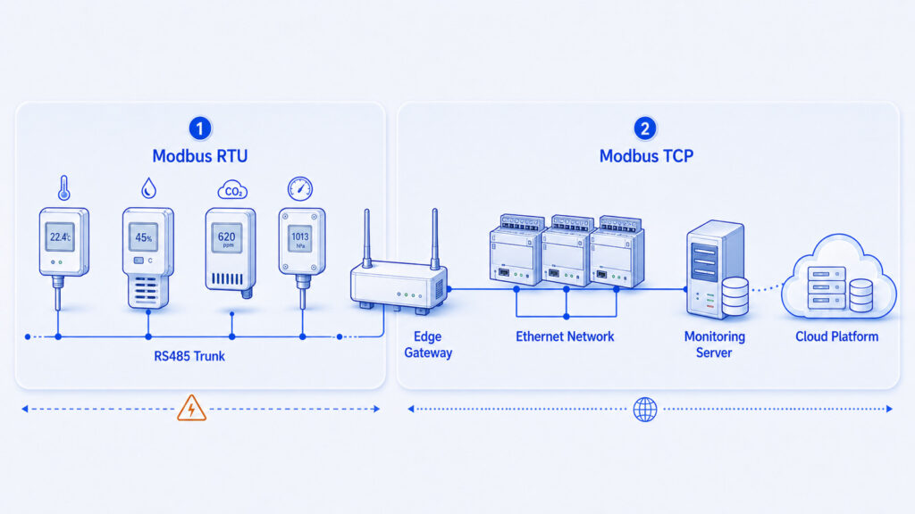
Modbus RTU often serves the sensor layer, while Modbus TCP connects the edge gateway to higher-level systems.
1.Quick Summary
| Option | How it works | Best suited for | Main advantage | Main limitation |
| Modbus RTU | Binary Modbus frames over asynchronous serial communication, commonly RS485. | Distributed field sensors, existing serial instruments and low-bandwidth multidrop networks. | Simple wiring and broad device support. | Shared bus timing, physical-layer faults and limited native security. |
| Modbus TCP | Modbus protocol data units carried in TCP/IP with an MBAP header. | Ethernet-connected controllers, gateways, BMS, SCADA and software integration. | Standard IP networking and easier system-level integration. | Larger attack surface and non-deterministic network behavior. |
| Hybrid gateway | Polls RTU sensors and exposes their registers through Modbus TCP or another northbound protocol. | Projects retaining serial sensors while adding cloud or enterprise connectivity. | Separates field wiring from higher-level networks. | Gateway mapping, capacity and failure behavior must be engineered. |
2.What Are Modbus RTU, Modbus TCP and RS485?
Modbus is an application-layer protocol for exchanging process data between intelligent devices. It defines function codes, a data model and request-response behavior, but it does not by itself define the electrical cable used between devices. The Modbus Organization currently lists the Modbus Application Protocol Specification V1.1b3, the Serial Line Protocol and Implementation Guide V1.02 and the Modbus Messaging on TCP/IP Implementation Guide V1.0b as the main implementation references. [1]
Modbus RTU is a compact binary transmission format for serial communication. In environmental monitoring, it is commonly carried over a two-wire, half-duplex RS485 network. RS485, formally associated with the TIA-485 family of electrical interface standards, defines differential signaling and driver-receiver behavior. It does not define Modbus addresses, register maps or function codes. A sensor can therefore use RS485 with a non-Modbus protocol, and Modbus RTU can also be carried over other serial interfaces in some products.
Modbus TCP carries the Modbus protocol data unit through TCP/IP, normally over Ethernet. The core function code and data semantics remain familiar, but the serial address and cyclic redundancy check are replaced by a Modbus Application Protocol header, commonly called the MBAP header, plus the integrity mechanisms of TCP/IP and the underlying link. Standard Modbus TCP normally uses TCP port 502. [1][2]
The Modbus Organization now uses the terms client and server. The client initiates a request; the server processes it and returns data or an exception response. Older manuals may still use the legacy terms master and slave, so engineers often encounter both vocabularies in installed systems. [3]
3.Why Does the Choice Matter in Environmental Monitoring?
An environmental monitoring system may need to collect temperature, relative humidity, carbon dioxide, differential pressure, soil moisture, wind speed, particulate matter or water-leak data from many locations. The sensing value may update only once every few seconds or minutes, yet the network still has to preserve device identity, timestamps, scaling, alarm continuity and data quality.
A greenhouse or plant may already have many RS485 probes, while a building platform may expect Ethernet controllers. A controlled warehouse may keep serial sensors at the field layer and use a gateway for caching and platform integration. The decision therefore depends on topology, maintenance and failure consequences more than headline bandwidth.
Key distinction
RS485 answers the question “How are electrical signals carried on the field cable?” Modbus RTU answers “How are serial requests and responses framed?” Modbus TCP answers “How are Modbus requests transported across an IP network?”
4.How Does a Modbus RTU Sensor Network Work?
A typical RS485 Modbus RTU network contains one active client and several addressed servers. The client requests one device at a time and waits for a response or timeout. Address 0 is broadcast, while normal server addresses are generally 1 through 247. [2]
The RS485 Physical Bus
The most reliable physical layout is a linear trunk, often described as a daisy chain, with short device stubs. The differential pair should use cable appropriate for the signaling rate and installation environment. Termination should match the cable characteristic impedance and be placed at the two physical ends of the trunk, not at every sensor. A value near 120 ohms is common for many industrial twisted-pair cables, but the correct value is a property of the cable and interface design rather than a universal rule.
Biasing keeps the bus in a defined idle state and is normally controlled at one point per segment. Star branches, long stubs, mixed reference potentials, loose terminals and reversed conductors can cause intermittent faults. Because A/B and D+/D- labels vary by vendor, confirm polarity from each manual.
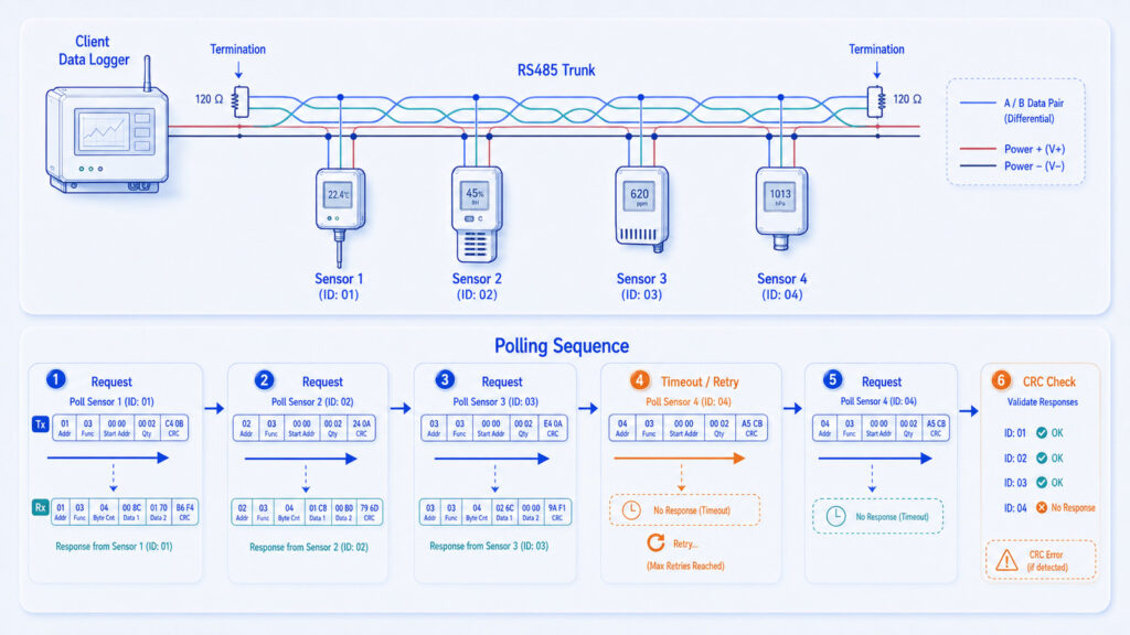
Reliable Modbus RTU depends on both protocol timing and correct RS485 bus construction.
The RTU Frame and Timing
| Field | Size | Purpose |
| Server address | 1 byte | Identifies the target serial device; address 0 is broadcast. |
| Function code | 1 byte | Specifies an operation such as reading holding registers or input registers. |
| Data | Variable | Carries starting address, quantity, values or exception information. |
| CRC | 2 bytes | Detects transmission errors in the RTU frame; it does not provide authentication or encryption. |
RTU frames are delimited by timing. The serial-line guide defines an inter-frame silent interval of at least 3.5 character times and limits gaps inside a frame. Response timeouts must cover device processing without allowing one failed server to stall the whole scan.
The CRC detects many bit errors caused by noise, wiring or timing problems. A CRC error means the received frame did not match the transmitted data, but it does not prove where the problem occurred. Common causes include wrong baud rate or parity, poor grounding, reflections, duplicate addresses, collisions caused by multiple active clients, weak transceivers, damaged cable and premature direction switching in an RS485 converter.
Polling Capacity and Update Time
On a shared half-duplex RTU bus, update time grows with device count, register count, retries and timeouts. Group contiguous registers and avoid unnecessary reads; a higher baud rate cannot overcome slow sensor conversion or inefficient single-register polling.
Calculate the worst-case scan, including processing, delays, retries and offline-device timeouts. Alarm-critical points may need a faster polling group than diagnostics.
5.How Does Modbus TCP Work?
Modbus TCP carries the same function codes and register concepts through TCP. Its seven-byte MBAP header contains Transaction Identifier, Protocol Identifier, Length and Unit Identifier. These fields match responses, identify Modbus, define message length and route requests through gateways.
| Field | Size | Purpose |
| Transaction Identifier | 2 bytes | Matches a response to the correct request. |
| Protocol Identifier | 2 bytes | Zero for standard Modbus TCP. |
| Length | 2 bytes | Counts the following bytes in the Modbus TCP message. |
| Unit Identifier | 1 byte | Identifies a downstream unit, particularly through a gateway. |
| Function code + data | Variable | Carries the Modbus protocol data unit. |
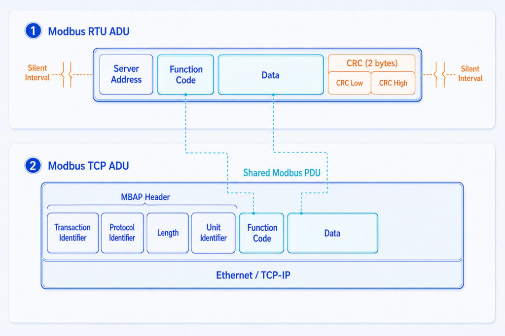
RTU and TCP share the Modbus function and data model but use different transport framing.
Modbus TCP does not append the RTU CRC because integrity checks already exist in Ethernet and TCP. That does not make the application secure: traditional Modbus TCP still lacks native user authentication, authorization and confidentiality. The Modbus Security specification addresses this gap by combining Modbus with Transport Layer Security, X.509v3 certificates and a dedicated port 802, but support must be confirmed on every device and software component. [1]
Ethernet simplifies integration with SCADA, BMS, historians and engineering tools, but adds switches, routing, firewalls and session limits. Multiple client connections may be supported, yet concurrency and update behavior are device-specific; a small gateway can become the bottleneck under heavy polling.
6.Which Parameters and Data-Model Details Matter?
| Parameter | Meaning | Why it matters |
| Baud rate / Ethernet link | Physical or link speed | Affects transmission time but not sensor conversion time or server processing time. |
| Parity and stop bits | Serial framing settings | Every RTU device on the segment must use compatible settings. |
| Server address / Unit ID | Target identity | Duplicate or incorrect identifiers route requests to the wrong device or no device. |
| Function code | Register-table operation | Input and holding registers are not interchangeable even when addresses look similar. |
| Register offset | Address sent in the request | Software may expect zero-based offsets or human-readable 3xxxx/4xxxx references. |
| Data type and scaling | Meaning of register values | Raw integers may require scale factors, signed interpretation or bit decoding. |
| Byte and word order | Ordering inside multi-register values | 32-bit integers and floats may be arranged differently by different vendors. |
| Timeout and retries | Failure handling | Too short creates false alarms; too long delays the complete scan. |
| Polling interval | How often data are requested | Controls freshness, bus load, network traffic and device workload. |
Register Maps: Where Most Integration Errors Begin
Modbus registers are 16 bits. Labels such as 30001 and 40001 are manual and software conventions; their leading digits are not transmitted. Requests use a zero-based offset, so holding register 40001 may be entered as 0, 1 or 40001 depending on the client. Verify the software convention, function code and device map.
Vendors often combine two 16-bit registers for 32-bit integers or floating-point values, and the order of those registers can vary. A plausible but incorrect reading often indicates scaling or word-order error rather than sensor failure.
7.Modbus RTU vs Modbus TCP: The Engineering Comparison
| Dimension | Modbus RTU | Modbus TCP |
| Physical infrastructure | Serial cable, commonly two-wire RS485. | Ethernet and IP infrastructure. |
| Framing | Address + function + data + CRC, delimited by timing. | MBAP header + function + data inside TCP. |
| Typical topology | Shared multidrop trunk with one initiating client. | Switched network with one or more clients and servers. |
| Error detection | Modbus CRC plus serial hardware checks. | Ethernet/TCP integrity checks; no Modbus CRC. |
| Throughput | Limited by baud rate, half-duplex polling and server response. | Usually higher transport capacity, but device processing remains a limit. |
| Distance | Can suit long field runs when engineered for cable and baud rate. | Copper Ethernet segments have network-design limits; fiber and switches can extend the system. |
| Integration | Often needs a serial port, converter or gateway. | Directly accessible to IP-based BMS, SCADA and software. |
| Security exposure | No built-in authentication or encryption; physical access matters. | No built-in protection in traditional Modbus TCP and greater network exposure. |
| Troubleshooting focus | Polarity, termination, bias, baud, parity, timing and CRC. | IP address, subnet, port, sessions, routing, firewall and application mapping. |
| Best fit | Simple field sensors and legacy industrial instruments. | Ethernet controllers, gateways and system-level integration. |
Selection rule
Choose Modbus RTU when the field devices are serial, data volumes are modest and a shared cable is practical. Choose Modbus TCP when the device or gateway is already on Ethernet and software integration matters. Use a hybrid gateway when serial sensors must be retained but higher-level systems require IP connectivity.
8.What Changes Performance in a Real Installation?
Cable, Topology and Electromagnetic Environment
RS485 performance depends on signaling rate, cable impedance, branch length, connectors, grounding and interference. Avoid long star branches unless a repeater creates compliant segments, and separate communication wiring from variable-frequency drive outputs and high-current switching cables.
Sensor Power and Ground Reference
Many RS485 sensors also need local DC power. Voltage drop may become the limit before communication distance, so measure the farthest sensor under load. Non-isolated nodes must also keep common-mode voltage within transceiver limits.
Polling Design and Gateway Capacity
A gateway has finite serial ports, queues, cache and TCP sessions. Multiple TCP clients polling one RTU bus can create stale data even when the wiring is sound. Where possible, use one controlled polling engine and serve cached values downstream.
OT Security
Neither standard Modbus RTU nor traditional Modbus TCP should be treated as a security boundary. CRC checks accidental corruption, not malicious commands. NIST SP 800-82 Rev. 3 recommends risk-based safeguards for operational technology while preserving performance, reliability and safety. Practical controls include network segmentation, firewall allowlists, least-privilege engineering access, secure remote-access paths, asset inventory, configuration backup, monitoring and physical protection. [4]
Where Modbus Security is unavailable, keep port 502 inside a controlled OT zone, use secure remote access and restrict write functions when the application only needs monitoring.
9.How Does Modbus Fit into a Complete AIoT Architecture?
In a complete environmental monitoring architecture, Modbus normally occupies the field and edge integration layers. Sensors expose measurements as input or holding registers. A controller, logger or gateway polls those registers, applies scaling and timestamps, performs local validation, stores data during network outages and forwards records to a platform. The northbound connection may use Modbus TCP, MQTT, HTTPS, an API or a vendor-specific secure service; these choices are independent of the field-side RS485 wiring.
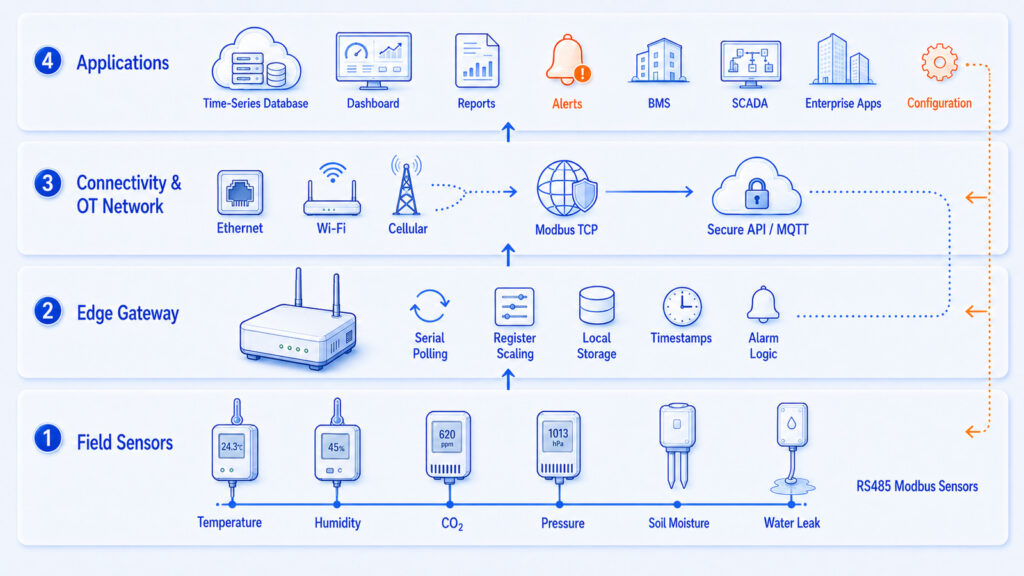
The edge gateway separates the serial field bus from cloud and enterprise integration.
| Layer | Role |
| Sensing layer | Temperature, humidity, CO2, pressure, soil, wind, water-leak and other probes. |
| Field network | RS485 multidrop segment using Modbus RTU. |
| Edge layer | Data logger or gateway for polling, scaling, timestamps, cache, alarms and protocol conversion. |
| Connectivity layer | Ethernet, Wi-Fi, cellular or another uplink; Modbus TCP may be used inside the OT network. |
| Platform layer | Time-series storage, dashboards, alarm rules, reports, APIs and device management. |
| Application layer | BMS, SCADA, cold chain, laboratory, greenhouse, manufacturing and maintenance workflows. |
The gateway separates failure domains. Local storage can preserve records during an uplink outage, but it cannot recover measurements lost because the serial bus failed. Monitor field communication and uplink status separately.
10.Which Applications Benefit Most?
| Application | Why the architecture fits |
| Industrial manufacturing | Existing transmitters often expose Modbus RTU; gateways integrate them with SCADA, but wiring and address control remain critical. |
| Building and data-center monitoring | Modbus TCP fits Ethernet BMS integration, while RTU remains common for meters and HVAC sensors. |
| Agriculture and greenhouses | RS485 connects distributed soil and climate sensors where radio is difficult; outdoor power drop and surge protection matter. |
| Laboratories and controlled storage | RTU probes support local acquisition while an edge logger handles timestamps and alarms; calibration remains a separate requirement. |
| Water and environmental stations | Low-data-rate instruments suit serial polling, but outdoor runs need grounding, surge protection and serviceable junctions. |
11.Limitations and Common Failure Modes
Modbus is widely supported because it is simple, not because it describes every engineering detail. It does not define sensor calibration, units, scaling, 32-bit data layout, time synchronization, alarm semantics or user access control. These responsibilities remain with the device vendor, integrator and system architecture.
| Symptom | Possible cause | Recommended check |
| No response from one RTU sensor | Wrong address, baud, parity, polarity, power or function code. | Verify power at the device, then test one sensor with a known-good client and exact manual settings. |
| All RTU devices fail intermittently | Termination, bias, grounding, reflections, noise or an extra active client. | Inspect the trunk, end termination, stubs, shield strategy and traffic capture. |
| Frequent CRC errors | Noise, timing mismatch, collisions, weak converter or damaged cable. | Compare serial settings, reduce baud temporarily, isolate sections and inspect waveform if possible. |
| Plausible but wrong value | Address offset, scaling, signed type, byte order or word order. | Read raw registers and decode them according to the vendor map. |
| TCP connection refused | Wrong IP/port, server disabled, firewall rule or session limit. | Confirm reachability, port 502 service, device connection limits and access policy. |
| Gateway data is stale | Serial timeouts, excessive polling, queue congestion or cache behavior. | Check per-device scan time, retry policy, gateway diagnostics and timestamp source. |
| Duplicate sensor identity | Two RTU devices share the same address. | Commission devices one at a time and maintain an address schedule. |
| Remote security concern | Port 502 exposed without segmentation or access control. | Place the system in an OT zone and use controlled remote access and allowlisting. |
12.How Should You Select and Implement the Protocol?
- Start with the device interface. If the required sensors expose only RS485 Modbus RTU, the field network decision is already constrained.
- Define point count, physical distance, cable route, environmental noise, power distribution and maintenance access before selecting baud rate or gateway hardware.
- Obtain a complete register map for every device, including function code, zero-based offset, data type, scale, units, byte order, valid range and exception behavior.
- Calculate worst-case polling time with retries and offline-device timeouts. Separate fast alarms from slow diagnostics when necessary.
- Design the RS485 trunk, stubs, termination, biasing, grounding and surge protection as one electrical system rather than individual sensor connections.
- Choose Modbus TCP when IP integration or multiple software applications justify Ethernet and its security controls.
- For a hybrid design, verify gateway capacity, register mapping, local cache, time source and failure behavior.
- Commission one sensor, one segment, the gateway and then the application; save known-good settings and traffic captures.
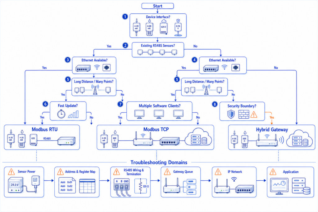
Choose the protocol from the physical device interface and integration requirement, then verify each failure domain.
When not to use Modbus alone
Do not rely on Modbus as the only mechanism when the project requires built-in semantic models, strong identity, encrypted end-to-end messaging, event-driven delivery or deterministic safety functions. A gateway or higher-level protocol may be needed, and safety-related control should follow the appropriate safety architecture and standards.
13.How Can UbiBot Use RS485 Modbus Sensors?
UbiBot lists several RS485 or Modbus RTU environmental probes, including temperature, humidity, soil, PT100 and wind options. Compatibility varies by probe and host model, so the official matrix should be checked. [5]
UbiBot support documentation describes enabling RS485 probes on compatible devices and viewing their data locally or remotely; it notes that WS1 does not support these probes. [6] The GS1-L page states support for standard Modbus RTU and multiple compatible RS485 sensors. [7]
This is a common hybrid pattern: Modbus RTU stays on the local bus while the edge device forwards measurements through a separate uplink. Confirm probe combinations, loading, power and firmware support for the selected model.
14.Frequently Asked Questions
What is the main difference between Modbus RTU and Modbus TCP?
Modbus RTU uses timed binary frames on a serial link, commonly RS485. Modbus TCP carries the same function and register concepts through TCP/IP with an MBAP header. RTU uses a shared bus and CRC; TCP uses Ethernet, IP addresses and sessions. A gateway or dual-protocol device is required between them.
Is Modbus RTU the same as RS485?
No. RS485 is an electrical interface for differential serial signaling; Modbus RTU is a messaging and framing method. RS485 can carry other protocols, and Modbus RTU may be implemented over other serial interfaces. A complete RS485 Modbus network therefore needs compatible electrical wiring, matching serial settings, unique device addresses and a correct Modbus register map.
Can multiple RS485 sensors share one cable?
Yes. Each server needs a unique address, compatible serial settings and enough power. Use a trunk with short stubs, end termination and controlled biasing. Practical node count depends on transceiver loading, cable, signal rate, topology and device specifications.
Why do Modbus CRC errors occur?
CRC errors occur when the received RTU frame differs from the transmitted frame. Frequent causes include electrical noise, reflections, incorrect termination, wrong baud or parity, weak grounding, damaged cable, duplicate addresses, multiple clients transmitting, or an RS485 converter switching direction at the wrong time. Capture the raw traffic and isolate the network section by section instead of replacing sensors at random.
Does every RS485 network need a 120-ohm termination resistor?
The bus should be terminated to match the characteristic impedance of the cable at the two physical ends when reflections are significant. Around 120 ohms is common for many industrial twisted-pair cables, but it is not a universal value and should not be installed at every node. Short, slow networks may behave without termination, yet a design that depends on this accident has little noise margin.
Can Modbus RTU data be sent to the cloud?
Yes, through an edge device or gateway. It polls serial sensors, converts registers, adds timestamps and forwards records over Ethernet, Wi-Fi or cellular. The cloud side may use HTTPS, MQTT, an API or a vendor service. Local buffering helps preserve data during uplink outages.
Why does a Modbus register show an incorrect temperature?
The most common causes are address offset, wrong function code, scale factor, signed versus unsigned interpretation, byte order or 32-bit word order. First read the raw 16-bit registers without conversion. Then compare the exact offset and data format with the vendor register map. A value that changes logically but has the wrong magnitude usually indicates decoding rather than sensor failure.
Is Modbus TCP secure?
Traditional Modbus TCP does not provide authentication, authorization or encryption. It should be deployed inside a segmented OT environment with controlled access, firewall rules, monitoring and secure remote-access paths. The Modbus Security protocol adds TLS and X.509 certificate mechanisms on port 802, but support is not universal. Confirm the capabilities of every server, client and gateway before relying on it.
Which is faster, Modbus RTU or Modbus TCP?
Modbus TCP usually has much greater transport capacity, but the useful update rate may still be limited by sensor conversion time, controller processing, gateway queues and application polling. A well-designed RTU bus can easily support slow environmental measurements. Select the protocol based on required scan time, topology and integration rather than assuming that Ethernet speed alone improves measurement freshness.
15.Technical References
[1] Modbus Organization. Modbus Specifications and Implementation Guides. Current official index for Modbus Application Protocol V1.1b3, Serial Line Guide V1.02, Modbus TCP/IP guide and Modbus Security.
[2] Modbus Organization. An Introduction to Modbus. Overview of the application-layer protocol, RS485 use, addresses, function codes and register concepts.
[3] Modbus Organization. Modbus Organization Replaces Master-Slave with Client-Server. Official terminology announcement, July 9, 2020.
[4] National Institute of Standards and Technology. NIST SP 800-82 Rev. 3: Guide to Operational Technology Security. Final publication, September 2023; current final OT security guidance at the time of writing.
[5] UbiBot. External Sensors and Probes. Official catalog of compatible environmental probes, including RS485 and Modbus RTU models.
[6] UbiBot Support Center. Settings of Probes with RS485 Interface. Official setup workflow for selected RS485 probes and compatible devices.
[7] UbiBot. GS1-L LoRa Smart Sensor. Official product page describing standard Modbus RTU and external RS485 sensor support.