
UBiBot Logo
UBiBot Logo
  • UBiBot Logo
  • Home
  • Products

    NEW

  • Pricing
  • Support
  • About Us
  • Download
  • magnifying-glass  Search
  • magnifying-glass header-close
  • Sign in Sign in
    Public Web Console Public Web Console
    On-Premises App Center On-Premises App Center
  • Home
  • Products

    NEW

  • Pricing
  • Support
  • About us
  • Download
  •  Public Web Console
  •  On-Premises App Center
  • Where to Buy

Learn Hub

Explore Knowledge Academic Research In-depth Tech

Share

LinkedIn

Facebook

X (Twitter)

Newsletter Signup

Table of contents

    How Do Sensor Calibration, Drift, and Traceability Affect Measurement Accuracy?

    Direct Answer

    Sensor calibration establishes how a sensor’s indication relates to reference values under specified conditions. Drift is the time-dependent change in that indication, while metrological traceability links a measurement result to a recognized reference through a documented calibration chain, with uncertainty at every step. Together, these factors determine whether a reading is fit for a decision. No calibration removes uncertainty, and no single recalibration interval suits every deployment.

    Key Takeaway

    Sensor calibration is valuable only when it is connected to a defined measurement task. Drift explains why performance changes with time; traceability explains how a result is linked to a recognized reference; uncertainty explains how much doubt remains. For high-risk environmental monitoring, verify the calibration range, uncertainty, as-found history, installation conditions, and recalibration logic—not merely the certificate date or the number of digits on the display.
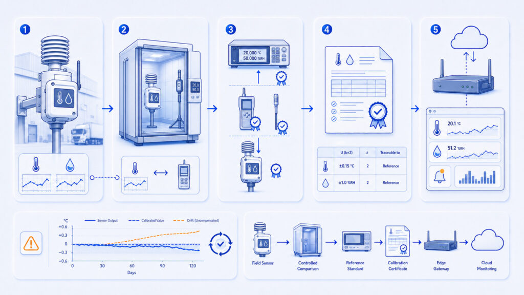
    sensor calibration, traceability chain and AIoT monitoring

    1.Quick Summary

    Question Answer
    What it is A measurement-assurance process that relates sensor indications to reference values and documents the associated uncertainty.
    How it works The sensor and a suitable reference are compared under controlled conditions across the required range; corrections and uncertainty are then evaluated.
    Best suited for Regulated storage, laboratories, research, cold chains, industrial monitoring, museums, and any application where a threshold or trend drives action.
    Main advantage Makes readings comparable, supports defensible decisions, and reveals bias or drift that a specification sheet cannot show.
    Main limitation Calibration is valid only for defined conditions and a period supported by stability evidence; it does not prevent future drift or installation error.
    Key decision factor The calibration uncertainty and range must be appropriate for the tolerance and risk of the actual monitoring task.

    2.What Do Calibration, Drift, Traceability, and Uncertainty Mean?

    Calibration is not simply a pass/fail test. The International Vocabulary of Metrology defines it as an operation that first establishes a relationship between reference values, their uncertainties, and the instrument’s indications, and then uses that relationship to obtain measurement results from future indications. Calibration may produce a correction, a curve, a table, or a model. It should not be confused with adjustment, which changes the instrument, or verification, which confirms whether a requirement is met. [1]

    Instrumental drift is a continuous or incremental change in indication over time caused by changes in the instrument’s metrological properties. Metrological traceability is a property of a measurement result—not a label permanently attached to a device. A result is traceable when it can be related to a stated reference through a documented, unbroken chain of calibrations, with each link contributing to the uncertainty. [1][3]

    Measurement uncertainty describes the dispersion of values that could reasonably be attributed to the measurand, based on the information available. It is not the same as error. Error is the difference between a measured value and a reference value; uncertainty quantifies the remaining doubt around the reported result. High display resolution does not by itself establish low uncertainty or high accuracy.

    3.Why Does Sensor Calibration Matter in Environmental Monitoring?

    Environmental monitoring systems often trigger decisions near a limit: release or quarantine a shipment, investigate a laboratory excursion, adjust a greenhouse, protect an archive, or escalate an equipment alarm. A small bias may be irrelevant in a broad comfort-monitoring application yet material when the permitted range is narrow. The technical question is therefore not simply whether a sensor can display temperature or humidity, but whether its measurement result is sufficiently reliable for the intended decision.

    Calibration contributes three forms of value. First, it identifies systematic deviation and supplies a correction when appropriate. Second, it provides evidence that measurements are linked to a recognized reference. Third, it creates historical data that can reveal drift and support a defensible recalibration interval. These benefits matter most when data must remain comparable across devices, sites, laboratories, seasons, or years.

    Traceability alone does not guarantee fitness for purpose. NIST emphasizes that a traceable result can still have uncertainty that is too large for the application. A monitoring program must compare the total measurement uncertainty with the process tolerance, alarm limit, regulatory requirement, or scientific objective. [3]

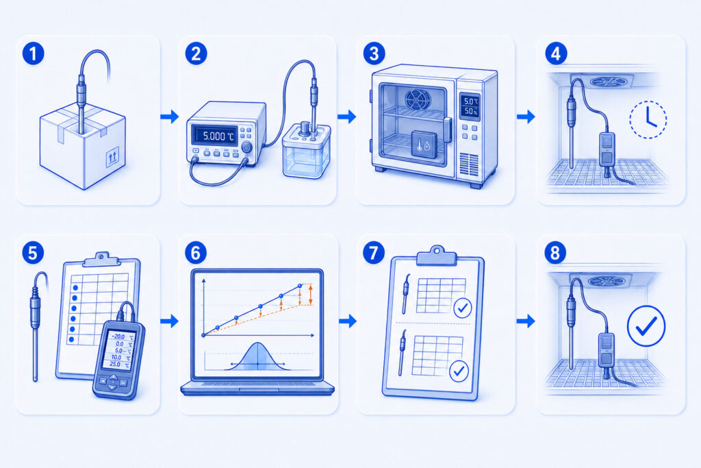
    4.How Does Sensor Calibration Work?

    A useful calibration begins with the measurement task rather than the sensor model. The required range, tolerance, environmental conditions, and decision risk determine the reference, number of points, stabilization time, and uncertainty target. A single point may be adequate for a narrow operating condition, but it cannot demonstrate performance across a wide range or reveal nonlinearity.

    During the comparison, the reference and device under test must experience the same condition. For temperature and humidity, chamber gradients, response-time differences, airflow, self-heating, cable conduction, and wall contact can create apparent error even when both instruments are functioning correctly. The calibration method must therefore control or quantify these effects.

    A complete result normally includes the measured deviation and the associated uncertainty. If an adjustment is made, the original as-found condition should be retained because it is the strongest evidence of how the device behaved during the preceding service interval. The final as-left result demonstrates performance after correction or adjustment.

    Stage What It Must Establish
    1. Define the measurand Specify what is being measured, where, over what range, and under which environmental and operating conditions.
    2. Select the reference Use a reference instrument or standard with documented calibration, uncertainty, range, and suitable resolution.
    3. Control the comparison Co-locate the sensor and reference, allow stabilization, manage airflow and thermal gradients, and record the setup.
    4. Measure multiple points Choose points that represent the operating range and decision limits; include repeated observations where practical.
    5. Calculate indication error Compare the sensor indication with the reference value and determine corrections, linearity, hysteresis, or model coefficients.
    6. Evaluate uncertainty Combine reference uncertainty, repeatability, resolution, environmental effects, interpolation, and other relevant components.
    7. Document the result Record as-found and as-left data, methods, conditions, uncertainty, traceability chain, limitations, and next review date.
    8. Verify after adjustment If an offset or other adjustment is applied, repeat the comparison to confirm the resulting performance.

    Working principle diagram placement: end-to-end calibration process

    6.Which Technical Parameters Control Calibration Quality?

    Calibration quality depends on the complete measurement system: the reference, method, environment, device, data handling, and operator. The most important parameters are summarized below.

    The target uncertainty should be defined before the work begins. If the reference and method cannot achieve an uncertainty small enough for the application, a technically correct calibration may still provide little decision value. Conversely, demanding extremely low uncertainty where the process tolerance is broad increases cost without improving the decision.

    Parameter Meaning Why It Matters
    Measurand and range The quantity, location, range, and operating condition being evaluated. A calibration outside the actual use range may not support the intended result.
    Reference uncertainty Uncertainty stated for the reference standard or instrument. Sets a lower bound on what the comparison can demonstrate.
    Repeatability Variation when the comparison is repeated under the same conditions. Reveals short-term random effects and contributes to Type A uncertainty.
    Resolution The smallest displayed or reported increment. Limits how finely changes can be observed but does not equal accuracy.
    Linearity and hysteresis Change in error across the range or between increasing and decreasing conditions. Determines whether one offset can correct the full range.
    Response and stabilization Time needed for the sensor and reference to reach equilibrium. Insufficient time produces false differences and unstable results.
    Environmental influence Effects from gradients, airflow, condensation, pressure, supply, or installation. May dominate the uncertainty outside controlled laboratory conditions.
    Drift and stability Change between calibrations or checks. Drives the risk of out-of-tolerance measurements and the recalibration interval.

    7.How Do Calibration, Verification, Adjustment, and Factory Calibration Differ?

    These activities solve different problems. Calibration characterizes the relationship between indication and reference. Verification asks whether a requirement is met. Adjustment changes the measuring system. Factory calibration describes where and when calibration occurred, but it does not by itself state the uncertainty, traceability chain, or suitability for a specific application.

    ISO/IEC 17025:2017 is the international standard used to assess the competence, impartiality, and consistent operation of testing and calibration laboratories; the current edition was confirmed in 2023. Accreditation to the standard provides confidence in a laboratory’s competence within its stated scope, but users still need to review the actual range, uncertainty, method, and certificate. [7]

    Activity What It Does Best Use Main Limitation
    Factory calibration Performed before shipment using the manufacturer’s process. Baseline quality control and general monitoring. Documentation, uncertainty, and traceability detail vary by supplier.
    Accredited traceable calibration Performed within a laboratory’s accredited scope using documented methods and uncertainty. Audits, regulated work, cross-site comparability, and high-risk decisions. Accreditation scope, range, uncertainty, and decision rule must match the task.
    Verification or intermediate check Confirms performance against a check standard or requirement between calibrations. Detecting drift and deciding whether service is needed. Does not automatically establish a new traceable calibration result.
    Adjustment or software offset Changes the device indication or reported value. Correcting known bias after a valid comparison. Must be documented and followed by verification; it is not calibration by itself.
    Replacement Removes an aging or damaged sensor from service. Low-cost devices, contamination, or repeated instability. New hardware still needs appropriate calibration evidence for the intended use.

    8.How Does Sensor Drift Change Measurement Accuracy Over Time?

    Drift develops after calibration as sensing elements and supporting electronics age or are exposed to stress. Causes are technology-specific and may include contamination, prolonged high humidity, thermal cycling, mechanical shock, chemical exposure, unstable power, radiation, or component aging. A correction established today does not guarantee the same bias months later.

    The most useful drift evidence is the as-found result from successive calibrations or intermediate checks. Plotting deviation over time can reveal whether change is random, steadily increasing, seasonal, or linked to events such as transport or exposure. Control charts and check standards help distinguish normal variation from a meaningful shift.

    When a device is out of tolerance before its scheduled recalibration, the response should go beyond adjusting it. The organization should assess affected historical data, determine when the condition may have started, review alarm or release decisions, identify the cause, and revise the interval or deployment controls. An instrument that repeatedly drifts may be unsuitable for the required environment even if it can be readjusted.

    9.How Is Measurement Uncertainty Evaluated?

    The Guide to the Expression of Uncertainty in Measurement separates evaluation methods into Type A and Type B. Type A components are evaluated statistically, such as the standard deviation from repeated observations. Type B components use other reliable information, including a reference certificate, previous data, manufacturer specifications, resolution, scientific judgment, or known environmental effects. [2][4]

    When components can reasonably be treated as independent and expressed as standard uncertainties, a simplified combined standard uncertainty is often calculated as the square root of the sum of their squares. Correlated components require a fuller treatment. Expanded uncertainty is then obtained by applying an appropriate coverage factor and reporting the coverage basis. A certificate should not present a number without explaining the method and coverage.

    Correction and uncertainty must remain separate. If a sensor reads 0.4 °C high at a test point, applying a −0.4 °C correction addresses the observed bias. It does not remove uncertainty arising from the reference, gradients, repeatability, resolution, drift, or the possibility that the correction changes elsewhere in the range.
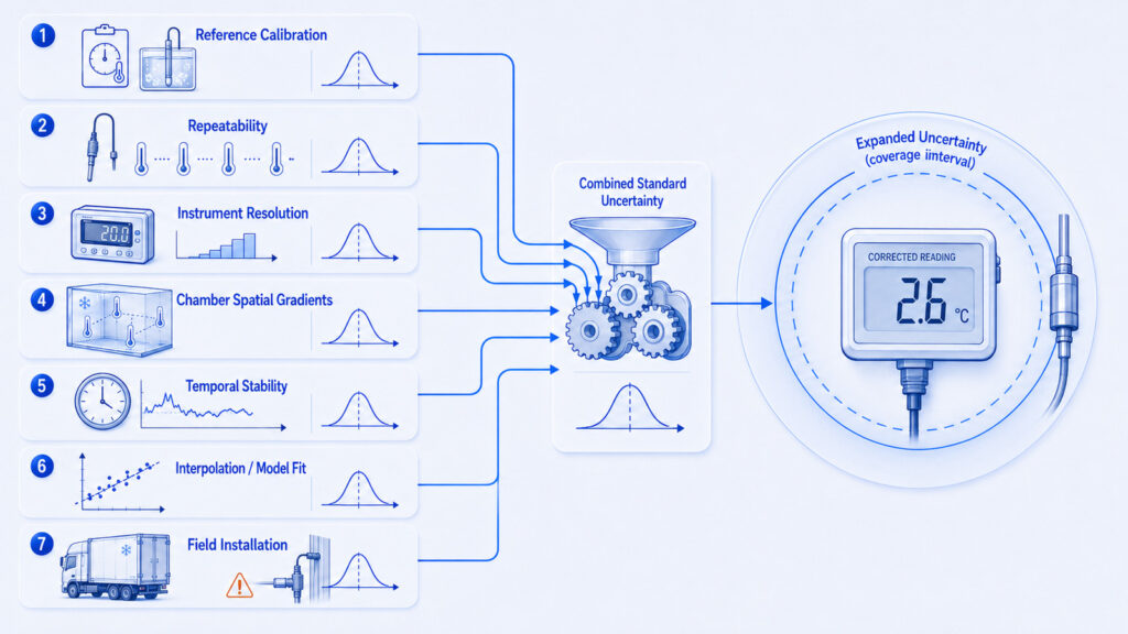
    Key parameter diagram placement: sensor uncertainty budget

    Uncertainty Component Typical Evidence or Mechanism
    Reference calibration Certificate uncertainty and any correction applied to the reference.
    Comparison repeatability Observed spread from repeated readings under stable conditions.
    Resolution and quantization Rounding or digital step size of the reference and device under test.
    Environmental non-uniformity Temperature or humidity gradients between the two sensing locations.
    Stability during the test Change in the chamber or source while readings are collected.
    Interpolation or model fit Uncertainty introduced when applying a calibration curve between tested points.
    Use conditions Installation, airflow, self-heating, cabling, condensation, or other field influences.

    10.How Should a Calibration Interval Be Determined?

    There is no universal recalibration interval. NIST does not prescribe one and identifies application accuracy, contractual or regulatory requirements, instrument stability, and environmental factors as key inputs. It recommends using measurement-assurance data, including comparisons and control charts, to establish and refine an interval. [5]

    ILAC G24:2022 likewise treats the interval as a managed decision rather than a fixed calendar rule. An initial interval may come from manufacturer information, similar equipment, risk analysis, usage frequency, transport history, and environmental severity. It should then be revised using as-found calibration results, intermediate checks, repairs, failures, and observed drift. [6]

    A risk-based program may use shorter checks for devices close to critical limits, exposed to harsh conditions, or lacking stability history. Stable devices with several acceptable as-found results may justify a longer interval, provided no contract, regulation, or quality procedure requires otherwise. Intermediate verification can reduce risk without replacing scheduled traceable calibration.

    11.What Affects Calibration Results in Real Deployments?

    A laboratory certificate cannot compensate for poor field installation. The sensor must be placed where the measurand is meaningful, not where installation is convenient. A temperature sensor mounted against a cold wall, above a heat source, or inside a poorly ventilated enclosure may report a locally correct value that does not represent the monitored space.

    Calibration setups have similar risks. Temperature and humidity chambers may have spatial gradients; reference and test sensors may respond at different speeds; power or wireless communication may warm the enclosure; and condensation may temporarily alter humidity response. The reference and test sensor should be close enough to experience the same condition without touching each other or the chamber wall. Readings should be collected only after both are stable.

    Data settings also matter. A display may update less often than the underlying sensor, or a cloud value may be delayed by synchronization. During calibration, operators should understand the acquisition interval, display refresh, averaging, filtering, timestamp, and any offset already applied. Otherwise, two valid instruments can appear to disagree simply because they represent different times or processing states.

    12.How Should Calibration Data Fit into an AIoT Monitoring Architecture?

    In an AIoT system, traceability information should travel with the device record rather than remain in a separate filing cabinet. Useful metadata include the sensor and channel identifier, measurand, calibration date, certificate ID, reference, tested range, correction, uncertainty, due date, firmware or configuration version, and status. The platform should preserve who changed a correction and when.

    Where possible, systems should distinguish raw indication from corrected value and retain the version of the correction applied. Retroactively changing historical records without an audit trail can undermine data integrity. A cloud platform can also flag overdue calibration, identify sensors with abnormal divergence, and compare nearby devices to detect possible drift, but automated analytics do not establish metrological traceability by themselves.

    Alarm and conformance decisions should account for uncertainty where the risk justifies it. For example, an organization may use guard bands or a documented decision rule near a specification limit. The rule should be agreed before results are reviewed; otherwise, the same reading may be treated differently by different users.
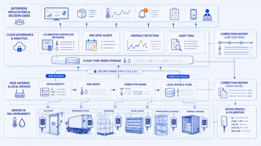
    AIoT architecture diagram placement: calibration metadata through the data lifecycle

    13.Where Are Traceable Measurements Most Important?

    The level of calibration control should match the consequence of a wrong decision. Trend-only monitoring may tolerate larger uncertainty than release testing, process validation, or scientific comparison. The table below shows how the same measurement principles translate into different applications.

    Application Measurement Need Calibration Focus
    Pharmaceutical and cold-chain monitoring Narrow operating limits, audit trails, and investigation of excursions. Use a traceable calibration program aligned with the required range; verify installation and assess uncertainty near alarm limits.
    Laboratories and research Comparable measurements across instruments, methods, sites, and time. Document the measurand, method, reference, uncertainty, and configuration so results can be reproduced.
    Museums, archives, and storage Long-term trend consistency for preservation decisions. Prioritize stability and cross-device comparability; use periodic checks to detect slow drift.
    Agriculture and controlled environments Distributed sensors exposed to moisture, contamination, and changing conditions. Use risk-based checks and protect sensors from exposure that can cause temporary or permanent bias.
    Industrial facilities and data centers Large point counts, remote alarms, and maintenance prioritization. Combine calibration metadata with device health, comparison checks, and service history.

    14.What Are the Common Failure Modes?

    Most calibration failures are not caused by arithmetic. They arise from an incomplete measurand definition, an unsuitable reference, poor stabilization, hidden configuration, or a traceability claim that is stronger than the evidence. A practical troubleshooting approach follows the measurement path from the physical environment to the sensor, device, correction, database, and decision.

    Symptom Possible Cause Recommended Check
    A certificate exists, but traceability is unclear The reference, uncertainty, method, or calibration chain is missing. Confirm the measured quantity, range, uncertainty, reference, laboratory scope, and certificate status.
    The sensor passes at room conditions but fails near the operating limit Too few calibration points, nonlinearity, or unsuitable range. Calibrate across the actual range and include decision points.
    Two calibrated sensors disagree in a chamber Spatial gradient, different response times, airflow, self-heating, or timestamp mismatch. Co-locate correctly, wait for stability, compare timestamps, and review acquisition settings.
    An offset corrects one point but worsens another The error is not constant across the range. Use a multi-point correction or replace the sensor; do not force a single offset.
    Drift is discovered before the due date Harsh exposure, shock, contamination, aging, or an interval that is too long. Assess historical impact, investigate cause, and shorten checks or change the sensor/environment.
    Historical data change after a new correction The platform applied an offset retroactively without version control. Preserve raw data and maintain an auditable correction history.

    15.How Should Users Build a Practical Calibration Program?

    Use traceable calibration when measurements support regulated, audited, contractual, safety-related, or scientific decisions. Factory calibration or internal comparison may be sufficient for low-risk trend monitoring with broad tolerances, but the organization should still verify that the device performs acceptably in its installation.

    Do not treat a familiar brand name, a high-resolution display, or the phrase ‘NIST traceable’ as complete evidence. Review the actual measurement result, reference, uncertainty, range, date, method, and chain of responsibility. The following sequence creates a defensible program without imposing laboratory-level control on every low-risk sensor.

    1. Define the decision, tolerance, measurement range, and target uncertainty.
    2. Identify each sensor, channel, probe, firmware version, and configuration that affects the result.
    3. Select a competent calibration provider and confirm that its scope, method, range, and uncertainty match the need.
    4. Specify points, stabilization criteria, orientation, power mode, acquisition interval, and environmental controls.
    5. Retain as-found results before any adjustment, because they support the assessment of prior data.
    6. Apply corrections or adjustments only through controlled procedures and record who made the change.
    7. Verify the as-left performance and document uncertainty, limitations, and traceability.
    8. Set the initial interval from risk and evidence, then refine it using drift and as-found history.
    9. Perform intermediate checks when a failure would have significant operational or compliance impact.
    10. Maintain calibration status and correction versions in the AIoT platform or asset-management system.

    When to use traceable calibration

    Use it when readings support release, validation, compliance, safety, contractual acceptance, cross-site comparison, or scientific claims. For low-risk trend monitoring, a verified factory-calibrated sensor may be adequate if its uncertainty and stability are appropriate for the decision.

    16.How Can UbiBot Users Apply These Principles?

    UbiBot’s current Calibration & Compliance guidance states that its devices include a factory calibration report with a two-year validity period and presents three renewal paths: calibration by a locally accredited laboratory, use of platform offset tools for internal QA/QC, or starting a new calibration cycle with a new device. The same guidance explicitly notes that platform self-calibration does not replace an external calibration certificate. [8]

    UbiBot support guidance also illustrates why the setup matters. For device checks, it recommends using a shorter acquisition interval, reducing or disabling synchronization that could create internal heat, allowing the device to stabilize, placing the device and reference together without blocking airflow, and using a calibrated or traceable reference instrument. These controls reduce comparison error, but the required laboratory competence, uncertainty, and certificate depend on the user’s application. [9]

    For regulated or high-risk use, purchasers should verify the exact model, probe, certificate scope, tested range, uncertainty, renewal route, and whether the result meets their internal procedure. A software offset is useful for controlled correction, but the original reading, correction value, date, operator, and supporting comparison should remain auditable.

    17.Frequently Asked Questions

    What is the difference between calibration and adjustment?

    Calibration determines the relationship between a sensor indication and reference values, including uncertainty. Adjustment changes the sensor or software so its indication is closer to a desired value. An adjustment should be followed by calibration or verification because changing an offset does not prove performance across the range. The pre-adjustment as-found result should be retained to assess the validity of data collected since the previous check.

    Does “NIST traceable” mean the sensor was calibrated by NIST?

    No. NIST explains that traceability is a property of a measurement result and may be established through an unbroken chain of calibrations leading to an appropriate reference. The work does not need to be performed directly by NIST. A credible claim should identify the reference, chain, measurement procedure, uncertainty, and responsible provider rather than relying on the phrase alone.

    How often should temperature and humidity sensors be calibrated?

    There is no universal interval. The appropriate period depends on the required accuracy, process risk, regulation or contract, device stability, operating environment, transport, usage, and prior as-found results. Start with manufacturer information and a risk assessment, then refine the interval using drift history and intermediate checks. A harsh or critical application may require more frequent verification than a stable, low-risk environment.

    Is a factory calibration certificate enough for a regulated application?

    Sometimes, but not automatically. Review whether the certificate identifies the device, measurand, range, reference, uncertainty, date, method, and traceability chain, and whether the issuing laboratory or manufacturer is accepted by your quality system. The calibration uncertainty must also be suitable for the required tolerance. A general certificate may not cover an external probe, the full operating range, or the specific channel used.

    Does higher sensor resolution mean higher measurement accuracy?

    No. Resolution is the smallest displayed or reported increment. A sensor can show 0.01 °C steps while having bias, drift, environmental sensitivity, or uncertainty much larger than 0.01 °C. Accuracy and fitness for purpose depend on the complete measurement system, including calibration, stability, installation, reference quality, and data processing.

    Is a one-point calibration sufficient?

    It can be sufficient for a narrow and stable operating point when the sensor response is known to be linear and the risk is low. It is not enough to demonstrate performance across a wide range or to detect nonlinearity and hysteresis. Multi-point calibration is usually more informative when monitoring spans several operating conditions or when limits occur at different parts of the range.

    Can a software offset correct sensor drift?

    A software offset can correct a known, approximately constant bias at the conditions tested. It cannot prove that the error is constant across the full range, remove random variation, reverse physical degradation, or eliminate uncertainty. Apply offsets through change control, preserve the original value when possible, and verify performance after the change.

    What should be done when a sensor is found out of tolerance?

    First preserve the as-found result and stop relying on the sensor for new critical decisions. Assess when the condition may have begun, which records and decisions could be affected, and whether nearby or redundant sensors provide evidence. Investigate exposure, damage, settings, and calibration history; then repair, adjust, recalibrate, or replace the sensor and revise the interval or deployment controls.

    18.Technical References

    [1] Joint Committee for Guides in Metrology (JCGM). International Vocabulary of Metrology — Basic and General Concepts and Associated Terms (VIM), JCGM 200:2012.

    [2] JCGM. Evaluation of Measurement Data — Guide to the Expression of Uncertainty in Measurement, JCGM 100:2008, with Amendment 1:2026 listed by BIPM.

    [3] NIST Technical Note 2156. Metrological Traceability: Frequently Asked Questions and NIST Policy. 2021.

    [4] NIST Technical Note 1297. Guidelines for Evaluating and Expressing the Uncertainty of NIST Measurement Results. 1994 edition; web guidance updated through 2026.

    [5] National Institute of Standards and Technology. Recommended Calibration Interval. Updated May 29, 2026.

    [6] International Laboratory Accreditation Cooperation. ILAC G24:2022 — Guidelines for the Determination of Recalibration Intervals of Measuring Equipment.

    [7] ISO/IEC 17025:2017. General Requirements for the Competence of Testing and Calibration Laboratories. Confirmed in 2023.

    [8] UbiBot. Calibration & Compliance: factory calibration, renewal options, and platform offset guidance. Accessed July 2026.

    [9] UbiBot. GS1 Support — Device Calibration Guidelines. Accessed July 2026.

    Related Resources

    Harbin Institute of Technology Uses UbiBot Sensors to Monitor Residential Indoor Temperature for Overheating and Shading Analysis
    University of South China Uses UbiBot GS1 to Monitor Temperature and Humidity in a Uranium Mill Tailings Pond Cover-Layer Experiment
    Modbus RTU vs Modbus TCP: How Do RS485 Sensor Networks Work?
    Thermocouple vs RTD vs Thermistor: Which Temperature Sensor Should You Choose?
    LoRaWAN vs Wi-Fi vs Cellular: Which Connectivity Is Best for Environmental Monitoring?
    UbiBot vs ELPRO vs Dickson vs Testo: Which Monitoring System Fits a GDP Pharmaceutical Warehouse?
    Beijing Jiaotong University and ETH Zurich Study Use UbiBot GS1 for Hygrothermal Monitoring in a Rural Poured Earth and Straw Building
    Laboratory Temperature & Humidity Monitor
    menu-header-svg
    Search
    • Explore Knowledge
      • Comparison & Selection
      • Industry Solution
      • Product & Device
      • Criterion & Compliance
      • Deployment & Usage
      • Technology & Principle
    • Academic Research
    • In-depth Tech

    In-depth Tech

    See More >>

    How Do Sensor Calibration, Drift, and Traceability Affect Measurement Accuracy?

    Direct Answer

    Sensor calibration establishes how a sensor’s indication relates to reference values under specified conditions. Drift is the time-dependent change in that indication, while metrological traceability links a measurement result to a recognized reference through a documented calibration chain, with uncertainty at every step. Together, these factors determine whether a reading is fit for a decision. No calibration removes uncertainty, and no single recalibration interval suits every deployment.

    Key Takeaway

    Sensor calibration is valuable only when it is connected to a defined measurement task. Drift explains why performance changes with time; traceability explains how a result is linked to a recognized reference; uncertainty explains how much doubt remains. For high-risk environmental monitoring, verify the calibration range, uncertainty, as-found history, installation conditions, and recalibration logic—not merely the certificate date or the number of digits on the display.

    sensor calibration, traceability chain and AIoT monitoring

    1.Quick Summary

    Question Answer
    What it is A measurement-assurance process that relates sensor indications to reference values and documents the associated uncertainty.
    How it works The sensor and a suitable reference are compared under controlled conditions across the required range; corrections and uncertainty are then evaluated.
    Best suited for Regulated storage, laboratories, research, cold chains, industrial monitoring, museums, and any application where a threshold or trend drives action.
    Main advantage Makes readings comparable, supports defensible decisions, and reveals bias or drift that a specification sheet cannot show.
    Main limitation Calibration is valid only for defined conditions and a period supported by stability evidence; it does not prevent future drift or installation error.
    Key decision factor The calibration uncertainty and range must be appropriate for the tolerance and risk of the actual monitoring task.

    2.What Do Calibration, Drift, Traceability, and Uncertainty Mean?

    Calibration is not simply a pass/fail test. The International Vocabulary of Metrology defines it as an operation that first establishes a relationship between reference values, their uncertainties, and the instrument’s indications, and then uses that relationship to obtain measurement results from future indications. Calibration may produce a correction, a curve, a table, or a model. It should not be confused with adjustment, which changes the instrument, or verification, which confirms whether a requirement is met. [1]

    Instrumental drift is a continuous or incremental change in indication over time caused by changes in the instrument’s metrological properties. Metrological traceability is a property of a measurement result—not a label permanently attached to a device. A result is traceable when it can be related to a stated reference through a documented, unbroken chain of calibrations, with each link contributing to the uncertainty. [1][3]

    Measurement uncertainty describes the dispersion of values that could reasonably be attributed to the measurand, based on the information available. It is not the same as error. Error is the difference between a measured value and a reference value; uncertainty quantifies the remaining doubt around the reported result. High display resolution does not by itself establish low uncertainty or high accuracy.

    3.Why Does Sensor Calibration Matter in Environmental Monitoring?

    Environmental monitoring systems often trigger decisions near a limit: release or quarantine a shipment, investigate a laboratory excursion, adjust a greenhouse, protect an archive, or escalate an equipment alarm. A small bias may be irrelevant in a broad comfort-monitoring application yet material when the permitted range is narrow. The technical question is therefore not simply whether a sensor can display temperature or humidity, but whether its measurement result is sufficiently reliable for the intended decision.

    Calibration contributes three forms of value. First, it identifies systematic deviation and supplies a correction when appropriate. Second, it provides evidence that measurements are linked to a recognized reference. Third, it creates historical data that can reveal drift and support a defensible recalibration interval. These benefits matter most when data must remain comparable across devices, sites, laboratories, seasons, or years.

    Traceability alone does not guarantee fitness for purpose. NIST emphasizes that a traceable result can still have uncertainty that is too large for the application. A monitoring program must compare the total measurement uncertainty with the process tolerance, alarm limit, regulatory requirement, or scientific objective. [3]

    4.How Does Sensor Calibration Work?

    A useful calibration begins with the measurement task rather than the sensor model. The required range, tolerance, environmental conditions, and decision risk determine the reference, number of points, stabilization time, and uncertainty target. A single point may be adequate for a narrow operating condition, but it cannot demonstrate performance across a wide range or reveal nonlinearity.

    During the comparison, the reference and device under test must experience the same condition. For temperature and humidity, chamber gradients, response-time differences, airflow, self-heating, cable conduction, and wall contact can create apparent error even when both instruments are functioning correctly. The calibration method must therefore control or quantify these effects.

    A complete result normally includes the measured deviation and the associated uncertainty. If an adjustment is made, the original as-found condition should be retained because it is the strongest evidence of how the device behaved during the preceding service interval. The final as-left result demonstrates performance after correction or adjustment.

    Stage What It Must Establish
    1. Define the measurand Specify what is being measured, where, over what range, and under which environmental and operating conditions.
    2. Select the reference Use a reference instrument or standard with documented calibration, uncertainty, range, and suitable resolution.
    3. Control the comparison Co-locate the sensor and reference, allow stabilization, manage airflow and thermal gradients, and record the setup.
    4. Measure multiple points Choose points that represent the operating range and decision limits; include repeated observations where practical.
    5. Calculate indication error Compare the sensor indication with the reference value and determine corrections, linearity, hysteresis, or model coefficients.
    6. Evaluate uncertainty Combine reference uncertainty, repeatability, resolution, environmental effects, interpolation, and other relevant components.
    7. Document the result Record as-found and as-left data, methods, conditions, uncertainty, traceability chain, limitations, and next review date.
    8. Verify after adjustment If an offset or other adjustment is applied, repeat the comparison to confirm the resulting performance.

    Working principle diagram placement: end-to-end calibration process

    6.Which Technical Parameters Control Calibration Quality?

    Calibration quality depends on the complete measurement system: the reference, method, environment, device, data handling, and operator. The most important parameters are summarized below.

    The target uncertainty should be defined before the work begins. If the reference and method cannot achieve an uncertainty small enough for the application, a technically correct calibration may still provide little decision value. Conversely, demanding extremely low uncertainty where the process tolerance is broad increases cost without improving the decision.

    Parameter Meaning Why It Matters
    Measurand and range The quantity, location, range, and operating condition being evaluated. A calibration outside the actual use range may not support the intended result.
    Reference uncertainty Uncertainty stated for the reference standard or instrument. Sets a lower bound on what the comparison can demonstrate.
    Repeatability Variation when the comparison is repeated under the same conditions. Reveals short-term random effects and contributes to Type A uncertainty.
    Resolution The smallest displayed or reported increment. Limits how finely changes can be observed but does not equal accuracy.
    Linearity and hysteresis Change in error across the range or between increasing and decreasing conditions. Determines whether one offset can correct the full range.
    Response and stabilization Time needed for the sensor and reference to reach equilibrium. Insufficient time produces false differences and unstable results.
    Environmental influence Effects from gradients, airflow, condensation, pressure, supply, or installation. May dominate the uncertainty outside controlled laboratory conditions.
    Drift and stability Change between calibrations or checks. Drives the risk of out-of-tolerance measurements and the recalibration interval.

    7.How Do Calibration, Verification, Adjustment, and Factory Calibration Differ?

    These activities solve different problems. Calibration characterizes the relationship between indication and reference. Verification asks whether a requirement is met. Adjustment changes the measuring system. Factory calibration describes where and when calibration occurred, but it does not by itself state the uncertainty, traceability chain, or suitability for a specific application.

    ISO/IEC 17025:2017 is the international standard used to assess the competence, impartiality, and consistent operation of testing and calibration laboratories; the current edition was confirmed in 2023. Accreditation to the standard provides confidence in a laboratory’s competence within its stated scope, but users still need to review the actual range, uncertainty, method, and certificate. [7]

    Activity What It Does Best Use Main Limitation
    Factory calibration Performed before shipment using the manufacturer’s process. Baseline quality control and general monitoring. Documentation, uncertainty, and traceability detail vary by supplier.
    Accredited traceable calibration Performed within a laboratory’s accredited scope using documented methods and uncertainty. Audits, regulated work, cross-site comparability, and high-risk decisions. Accreditation scope, range, uncertainty, and decision rule must match the task.
    Verification or intermediate check Confirms performance against a check standard or requirement between calibrations. Detecting drift and deciding whether service is needed. Does not automatically establish a new traceable calibration result.
    Adjustment or software offset Changes the device indication or reported value. Correcting known bias after a valid comparison. Must be documented and followed by verification; it is not calibration by itself.
    Replacement Removes an aging or damaged sensor from service. Low-cost devices, contamination, or repeated instability. New hardware still needs appropriate calibration evidence for the intended use.

    8.How Does Sensor Drift Change Measurement Accuracy Over Time?

    Drift develops after calibration as sensing elements and supporting electronics age or are exposed to stress. Causes are technology-specific and may include contamination, prolonged high humidity, thermal cycling, mechanical shock, chemical exposure, unstable power, radiation, or component aging. A correction established today does not guarantee the same bias months later.

    The most useful drift evidence is the as-found result from successive calibrations or intermediate checks. Plotting deviation over time can reveal whether change is random, steadily increasing, seasonal, or linked to events such as transport or exposure. Control charts and check standards help distinguish normal variation from a meaningful shift.

    When a device is out of tolerance before its scheduled recalibration, the response should go beyond adjusting it. The organization should assess affected historical data, determine when the condition may have started, review alarm or release decisions, identify the cause, and revise the interval or deployment controls. An instrument that repeatedly drifts may be unsuitable for the required environment even if it can be readjusted.

    9.How Is Measurement Uncertainty Evaluated?

    The Guide to the Expression of Uncertainty in Measurement separates evaluation methods into Type A and Type B. Type A components are evaluated statistically, such as the standard deviation from repeated observations. Type B components use other reliable information, including a reference certificate, previous data, manufacturer specifications, resolution, scientific judgment, or known environmental effects. [2][4]

    When components can reasonably be treated as independent and expressed as standard uncertainties, a simplified combined standard uncertainty is often calculated as the square root of the sum of their squares. Correlated components require a fuller treatment. Expanded uncertainty is then obtained by applying an appropriate coverage factor and reporting the coverage basis. A certificate should not present a number without explaining the method and coverage.

    Correction and uncertainty must remain separate. If a sensor reads 0.4 °C high at a test point, applying a −0.4 °C correction addresses the observed bias. It does not remove uncertainty arising from the reference, gradients, repeatability, resolution, drift, or the possibility that the correction changes elsewhere in the range.

    Key parameter diagram placement: sensor uncertainty budget

    Uncertainty Component Typical Evidence or Mechanism
    Reference calibration Certificate uncertainty and any correction applied to the reference.
    Comparison repeatability Observed spread from repeated readings under stable conditions.
    Resolution and quantization Rounding or digital step size of the reference and device under test.
    Environmental non-uniformity Temperature or humidity gradients between the two sensing locations.
    Stability during the test Change in the chamber or source while readings are collected.
    Interpolation or model fit Uncertainty introduced when applying a calibration curve between tested points.
    Use conditions Installation, airflow, self-heating, cabling, condensation, or other field influences.

    10.How Should a Calibration Interval Be Determined?

    There is no universal recalibration interval. NIST does not prescribe one and identifies application accuracy, contractual or regulatory requirements, instrument stability, and environmental factors as key inputs. It recommends using measurement-assurance data, including comparisons and control charts, to establish and refine an interval. [5]

    ILAC G24:2022 likewise treats the interval as a managed decision rather than a fixed calendar rule. An initial interval may come from manufacturer information, similar equipment, risk analysis, usage frequency, transport history, and environmental severity. It should then be revised using as-found calibration results, intermediate checks, repairs, failures, and observed drift. [6]

    A risk-based program may use shorter checks for devices close to critical limits, exposed to harsh conditions, or lacking stability history. Stable devices with several acceptable as-found results may justify a longer interval, provided no contract, regulation, or quality procedure requires otherwise. Intermediate verification can reduce risk without replacing scheduled traceable calibration.

    11.What Affects Calibration Results in Real Deployments?

    A laboratory certificate cannot compensate for poor field installation. The sensor must be placed where the measurand is meaningful, not where installation is convenient. A temperature sensor mounted against a cold wall, above a heat source, or inside a poorly ventilated enclosure may report a locally correct value that does not represent the monitored space.

    Calibration setups have similar risks. Temperature and humidity chambers may have spatial gradients; reference and test sensors may respond at different speeds; power or wireless communication may warm the enclosure; and condensation may temporarily alter humidity response. The reference and test sensor should be close enough to experience the same condition without touching each other or the chamber wall. Readings should be collected only after both are stable.

    Data settings also matter. A display may update less often than the underlying sensor, or a cloud value may be delayed by synchronization. During calibration, operators should understand the acquisition interval, display refresh, averaging, filtering, timestamp, and any offset already applied. Otherwise, two valid instruments can appear to disagree simply because they represent different times or processing states.

    12.How Should Calibration Data Fit into an AIoT Monitoring Architecture?

    In an AIoT system, traceability information should travel with the device record rather than remain in a separate filing cabinet. Useful metadata include the sensor and channel identifier, measurand, calibration date, certificate ID, reference, tested range, correction, uncertainty, due date, firmware or configuration version, and status. The platform should preserve who changed a correction and when.

    Where possible, systems should distinguish raw indication from corrected value and retain the version of the correction applied. Retroactively changing historical records without an audit trail can undermine data integrity. A cloud platform can also flag overdue calibration, identify sensors with abnormal divergence, and compare nearby devices to detect possible drift, but automated analytics do not establish metrological traceability by themselves.

    Alarm and conformance decisions should account for uncertainty where the risk justifies it. For example, an organization may use guard bands or a documented decision rule near a specification limit. The rule should be agreed before results are reviewed; otherwise, the same reading may be treated differently by different users.

    AIoT architecture diagram placement: calibration metadata through the data lifecycle

    13.Where Are Traceable Measurements Most Important?

    The level of calibration control should match the consequence of a wrong decision. Trend-only monitoring may tolerate larger uncertainty than release testing, process validation, or scientific comparison. The table below shows how the same measurement principles translate into different applications.

    Application Measurement Need Calibration Focus
    Pharmaceutical and cold-chain monitoring Narrow operating limits, audit trails, and investigation of excursions. Use a traceable calibration program aligned with the required range; verify installation and assess uncertainty near alarm limits.
    Laboratories and research Comparable measurements across instruments, methods, sites, and time. Document the measurand, method, reference, uncertainty, and configuration so results can be reproduced.
    Museums, archives, and storage Long-term trend consistency for preservation decisions. Prioritize stability and cross-device comparability; use periodic checks to detect slow drift.
    Agriculture and controlled environments Distributed sensors exposed to moisture, contamination, and changing conditions. Use risk-based checks and protect sensors from exposure that can cause temporary or permanent bias.
    Industrial facilities and data centers Large point counts, remote alarms, and maintenance prioritization. Combine calibration metadata with device health, comparison checks, and service history.

    14.What Are the Common Failure Modes?

    Most calibration failures are not caused by arithmetic. They arise from an incomplete measurand definition, an unsuitable reference, poor stabilization, hidden configuration, or a traceability claim that is stronger than the evidence. A practical troubleshooting approach follows the measurement path from the physical environment to the sensor, device, correction, database, and decision.

    Symptom Possible Cause Recommended Check
    A certificate exists, but traceability is unclear The reference, uncertainty, method, or calibration chain is missing. Confirm the measured quantity, range, uncertainty, reference, laboratory scope, and certificate status.
    The sensor passes at room conditions but fails near the operating limit Too few calibration points, nonlinearity, or unsuitable range. Calibrate across the actual range and include decision points.
    Two calibrated sensors disagree in a chamber Spatial gradient, different response times, airflow, self-heating, or timestamp mismatch. Co-locate correctly, wait for stability, compare timestamps, and review acquisition settings.
    An offset corrects one point but worsens another The error is not constant across the range. Use a multi-point correction or replace the sensor; do not force a single offset.
    Drift is discovered before the due date Harsh exposure, shock, contamination, aging, or an interval that is too long. Assess historical impact, investigate cause, and shorten checks or change the sensor/environment.
    Historical data change after a new correction The platform applied an offset retroactively without version control. Preserve raw data and maintain an auditable correction history.

    15.How Should Users Build a Practical Calibration Program?

    Use traceable calibration when measurements support regulated, audited, contractual, safety-related, or scientific decisions. Factory calibration or internal comparison may be sufficient for low-risk trend monitoring with broad tolerances, but the organization should still verify that the device performs acceptably in its installation.

    Do not treat a familiar brand name, a high-resolution display, or the phrase ‘NIST traceable’ as complete evidence. Review the actual measurement result, reference, uncertainty, range, date, method, and chain of responsibility. The following sequence creates a defensible program without imposing laboratory-level control on every low-risk sensor.

    1. Define the decision, tolerance, measurement range, and target uncertainty.
    2. Identify each sensor, channel, probe, firmware version, and configuration that affects the result.
    3. Select a competent calibration provider and confirm that its scope, method, range, and uncertainty match the need.
    4. Specify points, stabilization criteria, orientation, power mode, acquisition interval, and environmental controls.
    5. Retain as-found results before any adjustment, because they support the assessment of prior data.
    6. Apply corrections or adjustments only through controlled procedures and record who made the change.
    7. Verify the as-left performance and document uncertainty, limitations, and traceability.
    8. Set the initial interval from risk and evidence, then refine it using drift and as-found history.
    9. Perform intermediate checks when a failure would have significant operational or compliance impact.
    10. Maintain calibration status and correction versions in the AIoT platform or asset-management system.

    When to use traceable calibration

    Use it when readings support release, validation, compliance, safety, contractual acceptance, cross-site comparison, or scientific claims. For low-risk trend monitoring, a verified factory-calibrated sensor may be adequate if its uncertainty and stability are appropriate for the decision.

    16.How Can UbiBot Users Apply These Principles?

    UbiBot’s current Calibration & Compliance guidance states that its devices include a factory calibration report with a two-year validity period and presents three renewal paths: calibration by a locally accredited laboratory, use of platform offset tools for internal QA/QC, or starting a new calibration cycle with a new device. The same guidance explicitly notes that platform self-calibration does not replace an external calibration certificate. [8]

    UbiBot support guidance also illustrates why the setup matters. For device checks, it recommends using a shorter acquisition interval, reducing or disabling synchronization that could create internal heat, allowing the device to stabilize, placing the device and reference together without blocking airflow, and using a calibrated or traceable reference instrument. These controls reduce comparison error, but the required laboratory competence, uncertainty, and certificate depend on the user’s application. [9]

    For regulated or high-risk use, purchasers should verify the exact model, probe, certificate scope, tested range, uncertainty, renewal route, and whether the result meets their internal procedure. A software offset is useful for controlled correction, but the original reading, correction value, date, operator, and supporting comparison should remain auditable.

    17.Frequently Asked Questions

    What is the difference between calibration and adjustment?

    Calibration determines the relationship between a sensor indication and reference values, including uncertainty. Adjustment changes the sensor or software so its indication is closer to a desired value. An adjustment should be followed by calibration or verification because changing an offset does not prove performance across the range. The pre-adjustment as-found result should be retained to assess the validity of data collected since the previous check.

    Does “NIST traceable” mean the sensor was calibrated by NIST?

    No. NIST explains that traceability is a property of a measurement result and may be established through an unbroken chain of calibrations leading to an appropriate reference. The work does not need to be performed directly by NIST. A credible claim should identify the reference, chain, measurement procedure, uncertainty, and responsible provider rather than relying on the phrase alone.

    How often should temperature and humidity sensors be calibrated?

    There is no universal interval. The appropriate period depends on the required accuracy, process risk, regulation or contract, device stability, operating environment, transport, usage, and prior as-found results. Start with manufacturer information and a risk assessment, then refine the interval using drift history and intermediate checks. A harsh or critical application may require more frequent verification than a stable, low-risk environment.

    Is a factory calibration certificate enough for a regulated application?

    Sometimes, but not automatically. Review whether the certificate identifies the device, measurand, range, reference, uncertainty, date, method, and traceability chain, and whether the issuing laboratory or manufacturer is accepted by your quality system. The calibration uncertainty must also be suitable for the required tolerance. A general certificate may not cover an external probe, the full operating range, or the specific channel used.

    Does higher sensor resolution mean higher measurement accuracy?

    No. Resolution is the smallest displayed or reported increment. A sensor can show 0.01 °C steps while having bias, drift, environmental sensitivity, or uncertainty much larger than 0.01 °C. Accuracy and fitness for purpose depend on the complete measurement system, including calibration, stability, installation, reference quality, and data processing.

    Is a one-point calibration sufficient?

    It can be sufficient for a narrow and stable operating point when the sensor response is known to be linear and the risk is low. It is not enough to demonstrate performance across a wide range or to detect nonlinearity and hysteresis. Multi-point calibration is usually more informative when monitoring spans several operating conditions or when limits occur at different parts of the range.

    Can a software offset correct sensor drift?

    A software offset can correct a known, approximately constant bias at the conditions tested. It cannot prove that the error is constant across the full range, remove random variation, reverse physical degradation, or eliminate uncertainty. Apply offsets through change control, preserve the original value when possible, and verify performance after the change.

    What should be done when a sensor is found out of tolerance?

    First preserve the as-found result and stop relying on the sensor for new critical decisions. Assess when the condition may have begun, which records and decisions could be affected, and whether nearby or redundant sensors provide evidence. Investigate exposure, damage, settings, and calibration history; then repair, adjust, recalibrate, or replace the sensor and revise the interval or deployment controls.

    18.Technical References

    [1] Joint Committee for Guides in Metrology (JCGM). International Vocabulary of Metrology — Basic and General Concepts and Associated Terms (VIM), JCGM 200:2012.

    [2] JCGM. Evaluation of Measurement Data — Guide to the Expression of Uncertainty in Measurement, JCGM 100:2008, with Amendment 1:2026 listed by BIPM.

    [3] NIST Technical Note 2156. Metrological Traceability: Frequently Asked Questions and NIST Policy. 2021.

    [4] NIST Technical Note 1297. Guidelines for Evaluating and Expressing the Uncertainty of NIST Measurement Results. 1994 edition; web guidance updated through 2026.

    [5] National Institute of Standards and Technology. Recommended Calibration Interval. Updated May 29, 2026.

    [6] International Laboratory Accreditation Cooperation. ILAC G24:2022 — Guidelines for the Determination of Recalibration Intervals of Measuring Equipment.

    [7] ISO/IEC 17025:2017. General Requirements for the Competence of Testing and Calibration Laboratories. Confirmed in 2023.

    [8] UbiBot. Calibration & Compliance: factory calibration, renewal options, and platform offset guidance. Accessed July 2026.

    [9] UbiBot. GS1 Support — Device Calibration Guidelines. Accessed July 2026.

    分享

    LinkedIn2

    Facebook2

    X

    Newsletter Signup

    Related Resources

    Harbin Institute of Technology Uses UbiBot Sensors to Monitor Residential Indoor Temperature for Overheating and Shading Analysis
    University of South China Uses UbiBot GS1 to Monitor Temperature and Humidity in a Uranium Mill Tailings Pond Cover-Layer Experiment
    Modbus RTU vs Modbus TCP: How Do RS485 Sensor Networks Work?
    Thermocouple vs RTD vs Thermistor: Which Temperature Sensor Should You Choose?
    LoRaWAN vs Wi-Fi vs Cellular: Which Connectivity Is Best for Environmental Monitoring?
    UbiBot vs ELPRO vs Dickson vs Testo: Which Monitoring System Fits a GDP Pharmaceutical Warehouse?
    Beijing Jiaotong University and ETH Zurich Study Use UbiBot GS1 for Hygrothermal Monitoring in a Rural Poured Earth and Straw Building
    Laboratory Temperature & Humidity Monitor
    menu-header-svg
    Search
    • Explore Knowledge
      • Comparison & Selection
      • Industry Solution
      • Product & Device
      • Criterion & Compliance
      • Deployment & Usage
      • Technology & Principle
    • Academic Research
    • In-depth Tech
    Enter Your Information

    Confirm

    Products

    Dashboards

    Support

    Purchase

    Company

    Smart Sensing

    UbiBot Web Console

    APP Download

    UbiBot Online Store

    News

    Smart Control

    UbiBot Space

    Product Docs & APIs

    Find Distributors

    About Us

    Smart Video

    UbiBot On-Premises

    Helpdesk & FAQ

    Volume Pricing

    Contact Us

    LoRa Products

    Agency Web Console

    Video Center

    Architecture

    Software & Platform


    Pricing


    System Status

    External Sensors


    Become a Distributor

    Accessories


    Become an Affiliate

    Global SIM


    Positioning System


    Products

    Dashboards

    Business Partners

    WS1

    UbiBot Web Console

    Volume Pricing

    WS1 Pro

    UbiBot Space

    Become a Distributor

    GS1

    UbiBot Support Desk

    Affiliates

    GS2

    Agency Web Console


    MS1


    SP1


    Accessories


    Docs

    Purchase

    Company

    Platform API

    Pricing

    News

    Q&A

    UbiBot Partners

    About us

    Privacy Policy

    Online Store

    Contact

    Terms of Service


    System Status

    Products

    Dashboards

    Smart Sensing

    UbiBot Web Console

    Smart Control

    UbiBot Space

    Smart Video

    UbiBot On-Premises

    LoRa Products

    Agency Web Console

    Software & Platform


    External Sensors


    Accessories


    Global SIM


    Positioning System


    Support

    Purchase

    APP Download

    UbiBot Online Store

    Product Docs & APIs

    Find Distributors

    Helpdesk & FAQ

    Volume Pricing

    Video Center


    Pricing


    Company

    News

    About Us

    Contact Us

    Architecture

    System Status

    Become a Distributor

    Become an Affiliate

    Language:
    English 日本語 (ベータ)  
    Language:

    English

    日本語 (ベータ)


    IoT Product Family:
    ubibotico     Wireless environmental sensing products and smart building solutions
    ubitrackico     UWB-based real-time indoor tracking solutions with 30cm accuracy

    IoT Product Family:

    ubibotico  Wireless environmental sensing products and smart building solutions
    ubitrackico  UWB-based real-time indoor tracking solutions with 30cm accuracy

    © 2013-2026 UbiBot.com. All rights reserved.

    Terms of Service | Privacy Policy | Compliance

    youtube facebook twitter