
UBiBot Logo
UBiBot Logo
  • UBiBot Logo
  • Home
  • Products

    NEW

  • Pricing
  • Support
  • About Us
  • Download
  • magnifying-glass  Search
  • magnifying-glass header-close
  • Sign in Sign in
    Public Web Console Public Web Console
    On-Premises App Center On-Premises App Center
  • Home
  • Products

    NEW

  • Pricing
  • Support
  • About us
  • Download
  •  Public Web Console
  •  On-Premises App Center
  • Where to Buy

Learn Hub

Explore Knowledge Academic Research In-depth Tech

Share

LinkedIn

Facebook

X (Twitter)

Newsletter Signup

Table of contents

    Thermocouple vs RTD vs Thermistor: Which Temperature Sensor Should You Choose?

    Direct Answer

    Choose a thermocouple when temperature range, ruggedness or very high heat matters most; choose a platinum RTD when accuracy, repeatability and long-term stability are the priority; choose a thermistor when the range is limited and high sensitivity, small size or low cost matters. The sensor element alone does not determine performance: wiring, signal conditioning, installation, calibration and the complete measurement chain can change the final result.

    Key Takeaway

    The thermocouple vs RTD vs thermistor decision is not a ranking of “good, better, best.” It is a match between physical range, required uncertainty, response, environment, wiring and the available measurement interface. Thermocouples dominate extreme and rugged applications, platinum RTDs are the usual precision choice across moderate industrial ranges, and thermistors provide high sensitivity and compact low-cost measurement over narrower intervals. Verify the complete probe, electronics, installation and calibration before deployment.
     

    Thermocouple vs RTD vs thermistor

    1.Quick Summary

    Sensor How it works Best suited for Main advantage Main limitation
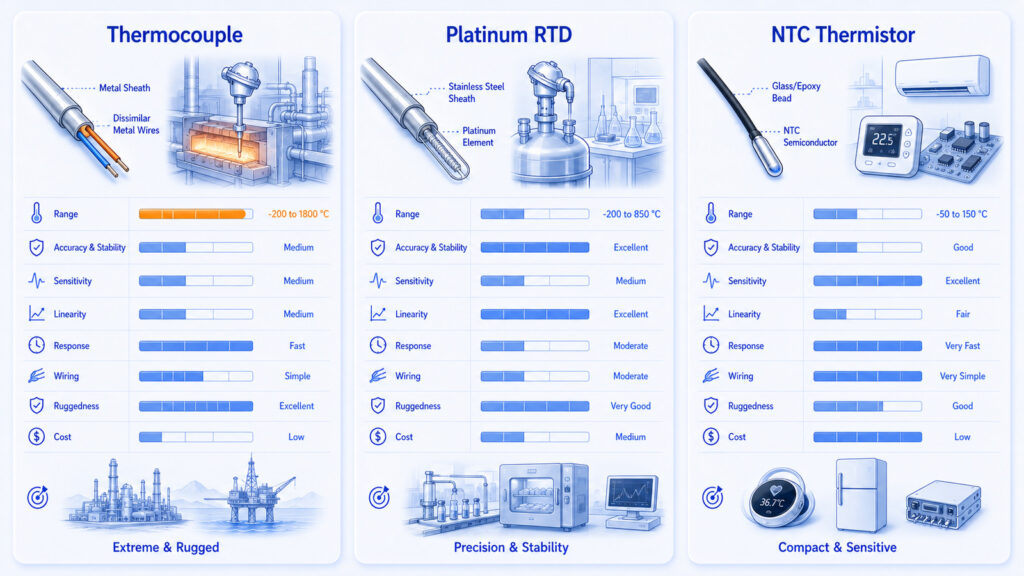
    Thermocouple Two dissimilar conductors generate a small thermoelectric voltage. Extreme or wide temperature ranges, rugged industrial probes. Wide range and simple sensing junction. Low signal level, nonlinear response and cold-junction compensation.
    RTD A metal element, usually platinum, changes resistance with temperature. Precision process, laboratory and regulated monitoring. Accuracy, repeatability, standardization and stability. Needs excitation; lead resistance and self-heating must be controlled.
    Thermistor A semiconductor resistor changes resistance strongly with temperature. Narrower-range electronics, appliances and compact probes. High sensitivity, small size and low cost. Strong nonlinearity, self-heating and manufacturer-specific curves.

    Thermocouple, RTD, thermistor comparison

    2.What Are Thermocouples, RTDs and Thermistors?

    Thermocouples, resistance temperature detectors (RTDs) and thermistors all convert temperature into an electrical quantity, but they do so through different physical mechanisms. That difference determines their useful range, signal level, linearity, wiring, calibration behavior and long-term stability. Treating them as interchangeable “temperature probes” is one of the most common causes of poor sensor selection.

    A thermocouple is a thermoelectric sensor. Two dissimilar conductors form a measuring junction and generate an electromotive force related to the temperature difference between that junction and a reference junction. IEC 60584-1 defines reference functions and tolerances for standardized letter-designated types, while the NIST ITS-90 database provides reference functions and tables for widely used types such as B, E, J, K, N, R, S and T. [1][2]

    An RTD is a resistance-based sensor made from a metal whose electrical resistance changes predictably with temperature. Platinum is preferred because its resistance-temperature relationship is stable and standardized. IEC 60751:2022 specifies requirements and the resistance-temperature relationship for industrial platinum resistance thermometers and sensors. A Pt100 element has a nominal resistance of 100 ohms at 0 °C. [3]

    A thermistor is also resistance-based, but it uses a semiconducting material rather than a pure metal. Negative temperature coefficient (NTC) thermistors decrease in resistance as temperature rises; positive temperature coefficient (PTC) thermistors increase in resistance. IEC 60539-1:2022 establishes generic terminology and test methods for directly heated NTC thermistors, while ASTM E879-20 covers NTC thermistor sensors for general-purpose and laboratory temperature measurement. [4][5]

    A Digital Temperature Sensor Is a Different Category

    A “digital temperature sensor” describes the output interface, not necessarily the sensing physics. A digital probe may contain an integrated-circuit sensor, an RTD with a transmitter, a thermistor with an analog-to-digital converter, or another sensing element. Because the signal has already been conditioned and digitized, a digital probe can be easier to connect to an IoT logger, but it must still be evaluated for range, accuracy, response time, calibration and environmental protection.

    3.How Does Each Temperature Sensor Work?
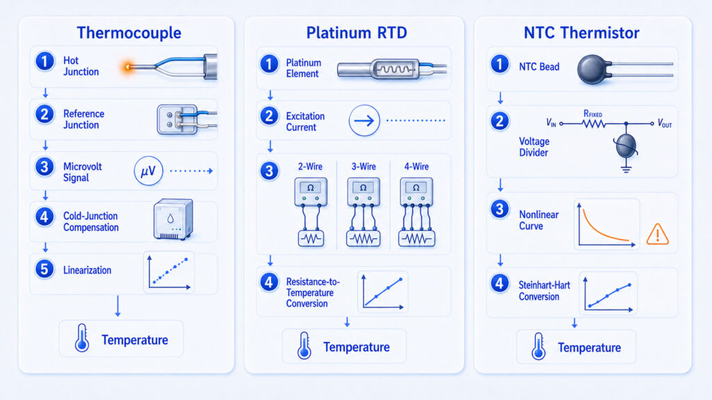
    How thermocouple RTD thermistor work

    Thermocouple: Measuring a Temperature Difference

    A thermocouple produces a small voltage through the Seebeck effect. The instrument does not measure the hot junction temperature directly; it measures thermoelectric voltage and uses the known reference function for the thermocouple type. The reading also depends on the terminal temperature at the instrument. Modern instruments measure this terminal temperature and apply cold-junction compensation (CJC). Without correct CJC, connector temperature changes appear as measurement error.

    The simplified relationship is Emeasured = E(Thot) – E(Treference). The voltage is small—often tens of microvolts per degree Celsius—so the input circuit needs low noise, appropriate amplification and protection against common-mode interference. Extension wire, connectors and terminal materials must match the thermocouple type or be designed as compensating materials. A wrong connector can create an unintended thermocouple junction.

    RTD: Measuring Resistance with Controlled Excitation

    An RTD requires a known excitation current or voltage. The measuring circuit reads the resulting voltage and calculates resistance, then converts resistance to temperature using the standardized curve. Over a limited range, the relationship can be approximated as Rt = R0(1 + alpha t), although precision instruments use the full standardized equation. The platinum coefficient and tolerance class must match the instrument configuration.

    Lead wires add resistance. A two-wire RTD includes lead resistance in the measurement, which can be significant for a Pt100 because the sensor changes by only about 0.385 ohm per degree Celsius near 0 °C. Three-wire circuits compensate lead resistance when the leads are well matched. Four-wire circuits separate excitation and measurement paths and are preferred when the lowest uncertainty is required. Excitation also causes self-heating, so current must be limited.

    Thermistor: High Sensitivity with a Nonlinear Curve

    An NTC thermistor is normally measured in a voltage divider or bridge circuit. Its resistance changes much more per degree than a platinum RTD, which gives high sensitivity and can simplify analog front-end design. The trade-off is a strongly nonlinear resistance-temperature relationship. The beta equation can approximate a limited range, while the Steinhart-Hart equation is commonly used for higher accuracy over a broader calibrated interval.

    Thermistors require excitation and therefore can self-heat. Their curves also vary by material system and manufacturer, so nominal resistance, beta value, tolerance and calibration coefficients must be treated as a matched data set. A replacement thermistor with the same resistance at 25 °C can still produce a different reading away from 25 °C if its curve is different. [7]

    4.Which Technical Parameters Matter Most?

    Parameter Meaning Why it matters
    Temperature range The interval over which the sensor and its construction remain within specified performance. A high-temperature element is useless if its cable, insulation or connector cannot tolerate the same environment.
    Accuracy / tolerance Maximum permitted deviation under stated conditions. Compare the complete probe and instrument, not only the bare element.
    Stability and drift Change in indicated temperature after time, thermal cycling or exposure. Long deployments may need recalibration even when initial accuracy is good.
    Sensitivity Electrical output change per degree. Higher sensitivity can improve signal-to-noise ratio but does not guarantee accuracy.
    Linearity How closely output follows a simple straight-line relationship. Nonlinear sensors need equations, lookup tables or multi-point calibration.
    Response time How quickly the assembly follows a temperature change. Probe diameter, sheath, airflow, immersion and mounting often dominate the sensor element.
    Self-heating Temperature rise caused by measurement current. Relevant to RTDs and thermistors, especially in still air or small samples.
    Lead-wire error Error caused by resistance, thermoelectric junctions or noise in cabling. The correct wire type and circuit topology are part of the measurement system.

    Accuracy Is a System Property

    Sensor tolerance is only one contributor to measurement uncertainty. The complete chain includes the sensing element, probe construction, reference-junction measurement or excitation source, analog front end, analog-to-digital converter, linearization, cable, connectors, installation, calibration reference and the temperature gradients between the sensor and the object being measured. A sensor with a tight datasheet tolerance can still report the wrong temperature if it is badly positioned or not in thermal equilibrium.

    5.Thermocouple vs RTD vs Thermistor: Engineering Comparison

    Criterion Thermocouple RTD Thermistor
    Operating principle Thermoelectric voltage from dissimilar conductors Metal resistance increases with temperature Semiconductor resistance changes strongly with temperature
    General range Widest; type and construction dependent, including cryogenic and very high temperatures Broad moderate range; IEC platinum sensors are standardized for industrial thermometry Usually narrower; commonly selected for limited measurement windows
    Accuracy and stability Moderate; depends strongly on type, wire homogeneity and CJC Generally strongest for repeatability, stability and standardized interchangeability Can be very accurate over a narrow calibrated range
    Linearity Nonlinear Near linear over useful ranges Strongly nonlinear
    Signal / excitation Self-generating low-level voltage; no excitation Requires precision excitation and resistance measurement Requires excitation and resistance measurement
    Wiring Correct thermocouple or compensation wire; CJC required 2-, 3- or 4-wire circuits Usually 2-wire
    Response potential Fast with exposed or small junctions Often slower in protective industrial assemblies Fast when the bead or chip is small
    Ruggedness Often high; suitable for vibration and high heat with the right sheath Good in industrial assemblies but the element can be more sensitive to shock Small and economical, but packaging determines robustness
    Typical cost position Low to moderate Moderate to high Low to moderate
    Best fit Furnaces, engines, exhausts, cryogenic or wide-range processes Precision process monitoring, laboratories, calibration and long-term monitoring Compact electronics, appliances and narrow-range control or monitoring

    Conditional Selection Rule

    Choose a thermocouple when the operating range exceeds practical RTD or thermistor limits, when the probe must be rugged, or when rapid response is more important than the lowest uncertainty. Choose an RTD when the temperature range is moderate and stable, repeatable measurements are required. Choose a thermistor when the range is limited and high sensitivity, compact size or low system cost is the main design driver.
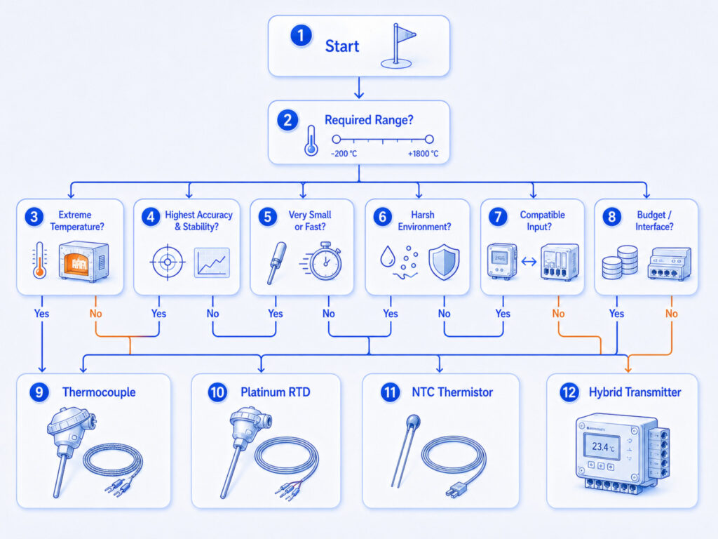
    Choose thermocouple, RTD or thermistor

    6.What Affects Accuracy in a Real Installation?

    Thermal Contact and Sensor Placement

    The sensor measures its own temperature, not automatically the temperature of the air, pipe, product or process. Heat conduction through a mounting bracket, cable or enclosure can bias the reading. Radiant heat from nearby equipment can warm an air sensor. A surface probe can read between the surface temperature and ambient temperature if contact pressure or insulation is poor. For immersion measurements, insufficient insertion depth allows stem conduction to pull heat toward the environment.

    Thermocouple-Specific Errors

    The most important thermocouple errors include incorrect type selection, wrong extension wire, connector material mismatch, poor cold-junction compensation, electrical noise and thermoelectric inhomogeneity after prolonged high-temperature exposure. A thermocouple can remain electrically continuous while its calibration has drifted. NIST guidance emphasizes wire condition, traceability and calibration of used thermocouples when uncertainty matters. [2]

    RTD-Specific Errors

    RTD errors often come from lead resistance, excitation-current self-heating, moisture ingress, insulation leakage, mechanical strain and incorrect alpha or tolerance-class settings. A three-wire circuit assumes similar lead resistances; if one conductor has a different length, gauge, terminal resistance or temperature, compensation is incomplete. Four-wire measurement reduces lead-resistance error but does not correct poor thermal contact or sensor drift.

    Thermistor-Specific Errors

    Thermistor errors commonly arise from using the wrong resistance-temperature coefficients, excessive excitation, insufficient linearization, moisture or aging, and a calibration interval that does not cover the actual operating range. Because thermistors are sensitive, small resistance errors in the divider resistor, ADC reference or connector can become visible temperature errors. Self-heating is most serious in still air, vacuum or small samples with limited heat capacity.

    7.Which Sensor Fits Common Environmental-Monitoring Applications?

    Application Main requirement Likely fit Important condition
    Cold rooms and pharmaceutical storage Stable, traceable measurements in a limited temperature range RTD or a calibrated digital sensor; thermistor can work when its full system is validated Probe placement and calibration usually matter more than extreme range.
    Industrial furnaces and exhausts High temperature, vibration and fast changes Thermocouple Select type, sheath and insulation for the atmosphere and maximum temperature.
    Laboratory reference or verification Low uncertainty and repeatability Platinum RTD Use 4-wire measurement, suitable calibration and immersion practice.
    Electronics and battery packs Small size, rapid local response and low cost NTC thermistor Design against self-heating and use the correct beta or Steinhart-Hart coefficients.
    Food processing and washdown Moisture resistance, cleanability and repeatable insertion RTD or thermocouple depending on temperature and response requirements Probe sheath, sealing and hygienic mounting can dominate selection.
    Engines and rotating machinery Wide range, vibration and ruggedness Thermocouple Route cables away from ignition noise and protect junctions from mechanical strain.

    Cold Storage Does Not Automatically Require an RTD

    Cold-chain projects often focus on a narrow band, but that does not by itself determine the sensor. A calibrated thermistor or digital sensor may provide adequate performance at lower cost, while an RTD may be justified when long-term stability, interchangeability or calibration practice is more important. The decision should start with the required maximum permissible error, response time, probe location, data logger compatibility and recalibration process—not with the sensor name alone.

    8.How Do These Sensors Fit into an AIoT Monitoring Architecture?

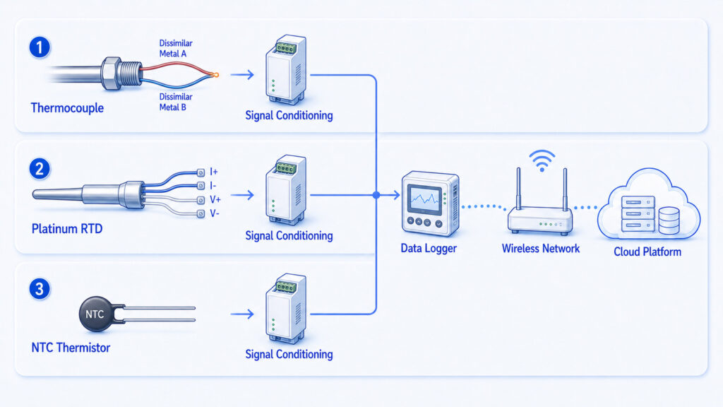
    The sensing element is only the first layer of an AIoT environmental-monitoring system. A practical architecture includes the probe, signal conditioning, analog-to-digital conversion, local processing, data logging, communications, cloud or on-premises storage, dashboards, alerts and integration with enterprise systems. The sensor output determines the front-end requirements: thermocouples need CJC and low-noise voltage measurement; RTDs need precision excitation and 2-, 3- or 4-wire resistance measurement; thermistors need excitation and nonlinear conversion.
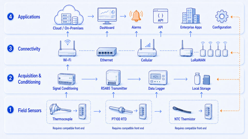
    Temperature sensor AIoT architecture

    For remote monitoring, the field device should timestamp readings, retain data when the network is unavailable, and synchronize buffered records after reconnection. Alarm logic should consider sensor faults separately from process alarms. An open thermocouple, shorted thermistor or disconnected RTD should not be interpreted as a genuine extreme temperature. The platform should preserve raw or engineering-unit data, calibration records and configuration changes when traceability is required.

    Interface Compatibility Must Be Verified

    A raw thermocouple cannot be connected to an RTD input, and a Pt100 cannot be connected to a generic voltage input without the correct transmitter or conditioning circuit. Connector shape alone proves nothing. Before procurement, confirm sensor type, nominal resistance or thermocouple letter type, wiring topology, excitation, measurement range, protocol, connector pinout, cable material and whether linearization is performed in the probe, logger or cloud platform.

    9.Limitations, Failure Modes and Troubleshooting

    Symptom Possible cause Recommended check
    Reading shifts with room temperature Thermocouple cold-junction compensation or terminal gradient problem Compare terminal temperature with a reference and inspect connector placement.
    RTD reads consistently high Lead resistance in a 2-wire circuit or excessive excitation self-heating Short the input to estimate lead error; reduce current and compare in a stirred bath.
    Thermistor agrees at 25 °C but not elsewhere Wrong beta value or Steinhart-Hart coefficients Verify the exact part curve and coefficients across multiple temperatures.
    Slow response Heavy sheath, poor contact, low airflow or insufficient immersion Test the complete probe in the actual medium; do not judge by element type alone.
    Noisy or unstable thermocouple reading Low-level signal pickup, grounding loop or damaged extension wire Check shielding, routing, grounding and continuity; confirm correct wire type.
    Sudden extreme value Open circuit, short circuit or moisture ingress Use sensor-fault diagnostics and inspect cable, connector and insulation resistance.
    Long-term drift Thermal cycling, contamination, strain or material aging Compare against a traceable reference and shorten the calibration interval if needed.

    No sensor technology eliminates the need for calibration. Calibration confirms the performance of the complete measurement chain at defined points and conditions. The interval should be based on risk, historical drift, exposure severity, regulatory or quality-system requirements and the consequences of an incorrect reading. A fixed annual interval is common, but it is not automatically appropriate for every process.

    10.A Practical Temperature Sensor Selection Process

    1. Define the actual minimum and maximum temperature, including startup, cleaning, sterilization, failure and storage conditions.
    2. Set the required system accuracy, repeatability, response time and acceptable drift—not just the sensor-element tolerance.
    3. Describe the medium and mounting: air, liquid, surface, pipe, product, vacuum, pressure, vibration, corrosion, moisture or washdown.
    4. Choose the physical probe construction before comparing electrical technologies. Sheath diameter and placement can dominate response.
    5. Check the complete signal chain: CJC for thermocouples; excitation and wiring for RTDs; coefficients and linearization for thermistors.
    6. Confirm cable length, connector materials, electromagnetic environment, ingress protection and maintenance access.
    7. Verify logger or controller compatibility, including input type, protocol, scaling, fault detection and data retention.
    8. Create a calibration and replacement plan. Interchangeability, traceability and downtime can outweigh the purchase price.

    When to Use Each Sensor

    Sensor Use it when Do not default to it when
    Thermocouple Use when very high or very low temperature, ruggedness, fast response or wide range is required. Avoid as the default precision sensor in a narrow, moderate range when CJC and drift would add unnecessary uncertainty.
    RTD Use when accuracy, stability, repeatability and standardization are priorities within a moderate range. Avoid when the environment exceeds the probe rating, shock is severe or response must be extremely fast.
    Thermistor Use when the range is limited and high sensitivity, small size or low cost is valuable. Avoid when wide interchangeability, broad range or simple linear conversion is required.

    11.UbiBot Implementation Example: Connecting an RTD to Remote Monitoring

    UbiBot officially lists a PT-100 temperature sensor with an RS485 interface among the external sensors supported by compatible WS1 Pro and GS1 configurations. The WS1 Pro product information identifies its lower Micro USB port as an RS485 interface for probes including PT-100, while UbiBot support documentation explains that the RS485 sensor must be enabled in the device settings. GS1 specifications also list PT-100 among supported external sensors on applicable RS485 models. [9][10][11]

    This implementation illustrates an important integration rule: the remote logger is not reading a bare platinum element directly. The PT-100 probe assembly and its transmitter provide the RS485 interface, and the compatible UbiBot device acquires the digital data for display, storage, alarms and remote access. Before deployment, users should confirm the exact device model, firmware, connector, power requirement, probe range and calibration documentation. These details can vary by model and sensor configuration.

    12.Frequently Asked Questions

    Which temperature sensor is the most accurate?

    No single sensor is always the most accurate. A well-designed platinum RTD system usually offers the strongest combination of accuracy, repeatability and long-term stability over a moderate range. A calibrated thermistor can achieve excellent accuracy over a narrow range, while a thermocouple is usually selected for range and ruggedness rather than minimum uncertainty. Installation and calibration can outweigh the element specification.

    Is a thermistor more accurate than an RTD?

    It can be over a limited calibrated interval. Thermistors have high sensitivity, so a carefully characterized thermistor and readout can resolve small changes. However, thermistor curves are strongly nonlinear and less standardized. RTDs are generally easier to interchange, more stable over a broad moderate range and more widely used for traceable industrial thermometry.

    Why does a thermocouple need cold-junction compensation?

    A thermocouple voltage represents the temperature difference between the measuring junction and the instrument terminals. The instrument must know the terminal temperature to calculate the measuring-junction temperature. Cold-junction compensation measures that reference temperature and applies the appropriate thermocouple reference function. Incorrect terminal sensing produces an error that follows the instrument environment.

    What is the difference between Pt100 and a thermistor?

    A Pt100 is a standardized platinum RTD with nominal resistance of 100 ohms at 0 °C. A thermistor is a semiconductor resistor, commonly an NTC type, with a much larger and more nonlinear resistance change. Pt100 sensors favor stability and standardization; thermistors favor sensitivity, small size and low cost over a narrower range.

    Can a thermocouple connect directly to an IoT data logger?

    Only if the logger has a compatible thermocouple input or a suitable transmitter is used. The input must support the correct thermocouple type, cold-junction compensation, low-level voltage measurement, linearization and fault detection. A generic analog input may not provide these functions, even if its voltage range appears suitable.

    Is a 3-wire RTD as accurate as a 4-wire RTD?

    A 3-wire RTD can be accurate when lead resistances are closely matched and the instrument compensates correctly. A 4-wire circuit measures voltage separately from excitation current, so lead resistance has much less influence. Four-wire measurement is preferred for calibration and low-uncertainty work, but three-wire systems are widely used in industrial control.

    What causes thermistor self-heating?

    Measurement current dissipates electrical power in the thermistor. If the surrounding medium cannot remove that heat, the thermistor becomes warmer than the object being measured and reports a biased temperature. Reduce excitation, use duty-cycled measurement, improve thermal contact or choose a larger dissipation constant when self-heating is significant.

    Which sensor is best for cold storage?

    The best choice depends on the required system accuracy, probe location, calibration process and logger interface. RTDs are attractive for stability and traceability; calibrated thermistors and digital probes can be practical for narrow cold-storage ranges; thermocouples are less common unless the range or mechanical environment justifies them. Validate the complete installed system.

     13.Technical References

    [1] International Electrotechnical Commission. IEC 60584-1:2013 – Thermocouples, Part 1: EMF Specifications and Tolerances. Edition 3.0, published 28 August 2013; stability date 2029.

    [2] National Institute of Standards and Technology. NIST Monograph 175 – Temperature-Electromotive Force Reference Functions and Tables for Letter-Designated Thermocouple Types Based on ITS-90. G. W. Burns et al., 1993; supporting NIST ITS-90 Thermocouple Database.

    [3] International Electrotechnical Commission. IEC 60751:2022 – Industrial Platinum Resistance Thermometers and Platinum Temperature Sensors. Edition 3.0, published 27 January 2022; stability date 2029.

    [4] International Electrotechnical Commission. IEC 60539-1:2022 – Directly Heated Negative Temperature Coefficient Thermistors, Part 1: Generic Specification. Edition 4.0, published 15 December 2022.

    [5] ASTM International. ASTM E879-20 – Standard Specification for Thermistor Sensors for General Purpose and Laboratory Temperature Measurements. Active standard for NTC thermistor-type sensors.

    [6] Analog Devices. Selecting Temperature Sensors for System Measurement and Protection. Design note comparing thermocouples, RTDs, thermistors and temperature-sensor ICs.

    [7] Analog Devices. Thermistor-Based Temperature Sensing System – Part 1: Design Challenges and Circuit Configuration. Technical discussion of NTC/PTC thermistors, RTD comparison, linearity and circuit trade-offs.

    [8] National Instruments. Measuring Temperature with Thermocouples, RTDs, and Thermistors. Sensor selection and signal-conditioning guide.

    [9] UbiBot. UbiBot WS1 Pro – Wireless Smart Sensor. Official product page describing external sensor and RS485 support.

    [10] UbiBot Support Center. Settings of Sensors with RS485 Interface. Updated 22 October 2025; lists PT-100 among UbiBot RS485 sensors and setup requirements.

    [11] UbiBot. UbiBot GS1 Specifications. Official model specifications and supported external sensors.


    Related Resources

    Modbus RTU vs Modbus TCP: How Do RS485 Sensor Networks Work?
    LoRaWAN vs Wi-Fi vs Cellular: Which Connectivity Is Best for Environmental Monitoring?
    How Do Sensor Calibration, Drift, and Traceability Affect Measurement Accuracy?
    Hot Spa & Ubibot in Cold Winter
    Many Customers’ Concerns: How to Monitor the Environment in Extremely Cold or Hot Conditions?
    menu-header-svg
    Search
    • Explore Knowledge
      • Comparison & Selection
      • Industry Solution
      • Product & Device
      • Criterion & Compliance
      • Deployment & Usage
      • Technology & Principle
    • Academic Research
    • In-depth Tech

    In-depth Tech

    See More >>

    Thermocouple vs RTD vs Thermistor: Which Temperature Sensor Should You Choose?

    Direct Answer

    Choose a thermocouple when temperature range, ruggedness or very high heat matters most; choose a platinum RTD when accuracy, repeatability and long-term stability are the priority; choose a thermistor when the range is limited and high sensitivity, small size or low cost matters. The sensor element alone does not determine performance: wiring, signal conditioning, installation, calibration and the complete measurement chain can change the final result.

    Key Takeaway

    The thermocouple vs RTD vs thermistor decision is not a ranking of “good, better, best.” It is a match between physical range, required uncertainty, response, environment, wiring and the available measurement interface. Thermocouples dominate extreme and rugged applications, platinum RTDs are the usual precision choice across moderate industrial ranges, and thermistors provide high sensitivity and compact low-cost measurement over narrower intervals. Verify the complete probe, electronics, installation and calibration before deployment.


    Thermocouple vs RTD vs thermistor

    1.Quick Summary

    Sensor How it works Best suited for Main advantage Main limitation
    Thermocouple Two dissimilar conductors generate a small thermoelectric voltage. Extreme or wide temperature ranges, rugged industrial probes. Wide range and simple sensing junction. Low signal level, nonlinear response and cold-junction compensation.
    RTD A metal element, usually platinum, changes resistance with temperature. Precision process, laboratory and regulated monitoring. Accuracy, repeatability, standardization and stability. Needs excitation; lead resistance and self-heating must be controlled.
    Thermistor A semiconductor resistor changes resistance strongly with temperature. Narrower-range electronics, appliances and compact probes. High sensitivity, small size and low cost. Strong nonlinearity, self-heating and manufacturer-specific curves.

    Thermocouple, RTD, thermistor comparison

    2.What Are Thermocouples, RTDs and Thermistors?

    Thermocouples, resistance temperature detectors (RTDs) and thermistors all convert temperature into an electrical quantity, but they do so through different physical mechanisms. That difference determines their useful range, signal level, linearity, wiring, calibration behavior and long-term stability. Treating them as interchangeable “temperature probes” is one of the most common causes of poor sensor selection.

    A thermocouple is a thermoelectric sensor. Two dissimilar conductors form a measuring junction and generate an electromotive force related to the temperature difference between that junction and a reference junction. IEC 60584-1 defines reference functions and tolerances for standardized letter-designated types, while the NIST ITS-90 database provides reference functions and tables for widely used types such as B, E, J, K, N, R, S and T. [1][2]

    An RTD is a resistance-based sensor made from a metal whose electrical resistance changes predictably with temperature. Platinum is preferred because its resistance-temperature relationship is stable and standardized. IEC 60751:2022 specifies requirements and the resistance-temperature relationship for industrial platinum resistance thermometers and sensors. A Pt100 element has a nominal resistance of 100 ohms at 0 °C. [3]

    A thermistor is also resistance-based, but it uses a semiconducting material rather than a pure metal. Negative temperature coefficient (NTC) thermistors decrease in resistance as temperature rises; positive temperature coefficient (PTC) thermistors increase in resistance. IEC 60539-1:2022 establishes generic terminology and test methods for directly heated NTC thermistors, while ASTM E879-20 covers NTC thermistor sensors for general-purpose and laboratory temperature measurement. [4][5]

    A Digital Temperature Sensor Is a Different Category

    A “digital temperature sensor” describes the output interface, not necessarily the sensing physics. A digital probe may contain an integrated-circuit sensor, an RTD with a transmitter, a thermistor with an analog-to-digital converter, or another sensing element. Because the signal has already been conditioned and digitized, a digital probe can be easier to connect to an IoT logger, but it must still be evaluated for range, accuracy, response time, calibration and environmental protection.

    3.How Does Each Temperature Sensor Work?

    How thermocouple RTD thermistor work

    Thermocouple: Measuring a Temperature Difference

    A thermocouple produces a small voltage through the Seebeck effect. The instrument does not measure the hot junction temperature directly; it measures thermoelectric voltage and uses the known reference function for the thermocouple type. The reading also depends on the terminal temperature at the instrument. Modern instruments measure this terminal temperature and apply cold-junction compensation (CJC). Without correct CJC, connector temperature changes appear as measurement error.

    The simplified relationship is Emeasured = E(Thot) – E(Treference). The voltage is small—often tens of microvolts per degree Celsius—so the input circuit needs low noise, appropriate amplification and protection against common-mode interference. Extension wire, connectors and terminal materials must match the thermocouple type or be designed as compensating materials. A wrong connector can create an unintended thermocouple junction.

    RTD: Measuring Resistance with Controlled Excitation

    An RTD requires a known excitation current or voltage. The measuring circuit reads the resulting voltage and calculates resistance, then converts resistance to temperature using the standardized curve. Over a limited range, the relationship can be approximated as Rt = R0(1 + alpha t), although precision instruments use the full standardized equation. The platinum coefficient and tolerance class must match the instrument configuration.

    Lead wires add resistance. A two-wire RTD includes lead resistance in the measurement, which can be significant for a Pt100 because the sensor changes by only about 0.385 ohm per degree Celsius near 0 °C. Three-wire circuits compensate lead resistance when the leads are well matched. Four-wire circuits separate excitation and measurement paths and are preferred when the lowest uncertainty is required. Excitation also causes self-heating, so current must be limited.

    Thermistor: High Sensitivity with a Nonlinear Curve

    An NTC thermistor is normally measured in a voltage divider or bridge circuit. Its resistance changes much more per degree than a platinum RTD, which gives high sensitivity and can simplify analog front-end design. The trade-off is a strongly nonlinear resistance-temperature relationship. The beta equation can approximate a limited range, while the Steinhart-Hart equation is commonly used for higher accuracy over a broader calibrated interval.

    Thermistors require excitation and therefore can self-heat. Their curves also vary by material system and manufacturer, so nominal resistance, beta value, tolerance and calibration coefficients must be treated as a matched data set. A replacement thermistor with the same resistance at 25 °C can still produce a different reading away from 25 °C if its curve is different. [7]

    4.Which Technical Parameters Matter Most?

    Parameter Meaning Why it matters
    Temperature range The interval over which the sensor and its construction remain within specified performance. A high-temperature element is useless if its cable, insulation or connector cannot tolerate the same environment.
    Accuracy / tolerance Maximum permitted deviation under stated conditions. Compare the complete probe and instrument, not only the bare element.
    Stability and drift Change in indicated temperature after time, thermal cycling or exposure. Long deployments may need recalibration even when initial accuracy is good.
    Sensitivity Electrical output change per degree. Higher sensitivity can improve signal-to-noise ratio but does not guarantee accuracy.
    Linearity How closely output follows a simple straight-line relationship. Nonlinear sensors need equations, lookup tables or multi-point calibration.
    Response time How quickly the assembly follows a temperature change. Probe diameter, sheath, airflow, immersion and mounting often dominate the sensor element.
    Self-heating Temperature rise caused by measurement current. Relevant to RTDs and thermistors, especially in still air or small samples.
    Lead-wire error Error caused by resistance, thermoelectric junctions or noise in cabling. The correct wire type and circuit topology are part of the measurement system.

    Accuracy Is a System Property

    Sensor tolerance is only one contributor to measurement uncertainty. The complete chain includes the sensing element, probe construction, reference-junction measurement or excitation source, analog front end, analog-to-digital converter, linearization, cable, connectors, installation, calibration reference and the temperature gradients between the sensor and the object being measured. A sensor with a tight datasheet tolerance can still report the wrong temperature if it is badly positioned or not in thermal equilibrium.

    5.Thermocouple vs RTD vs Thermistor: Engineering Comparison

    Criterion Thermocouple RTD Thermistor
    Operating principle Thermoelectric voltage from dissimilar conductors Metal resistance increases with temperature Semiconductor resistance changes strongly with temperature
    General range Widest; type and construction dependent, including cryogenic and very high temperatures Broad moderate range; IEC platinum sensors are standardized for industrial thermometry Usually narrower; commonly selected for limited measurement windows
    Accuracy and stability Moderate; depends strongly on type, wire homogeneity and CJC Generally strongest for repeatability, stability and standardized interchangeability Can be very accurate over a narrow calibrated range
    Linearity Nonlinear Near linear over useful ranges Strongly nonlinear
    Signal / excitation Self-generating low-level voltage; no excitation Requires precision excitation and resistance measurement Requires excitation and resistance measurement
    Wiring Correct thermocouple or compensation wire; CJC required 2-, 3- or 4-wire circuits Usually 2-wire
    Response potential Fast with exposed or small junctions Often slower in protective industrial assemblies Fast when the bead or chip is small
    Ruggedness Often high; suitable for vibration and high heat with the right sheath Good in industrial assemblies but the element can be more sensitive to shock Small and economical, but packaging determines robustness
    Typical cost position Low to moderate Moderate to high Low to moderate
    Best fit Furnaces, engines, exhausts, cryogenic or wide-range processes Precision process monitoring, laboratories, calibration and long-term monitoring Compact electronics, appliances and narrow-range control or monitoring

    Conditional Selection Rule

    Choose a thermocouple when the operating range exceeds practical RTD or thermistor limits, when the probe must be rugged, or when rapid response is more important than the lowest uncertainty. Choose an RTD when the temperature range is moderate and stable, repeatable measurements are required. Choose a thermistor when the range is limited and high sensitivity, compact size or low system cost is the main design driver.

    Choose thermocouple, RTD or thermistor

    6.What Affects Accuracy in a Real Installation?

    Thermal Contact and Sensor Placement

    The sensor measures its own temperature, not automatically the temperature of the air, pipe, product or process. Heat conduction through a mounting bracket, cable or enclosure can bias the reading. Radiant heat from nearby equipment can warm an air sensor. A surface probe can read between the surface temperature and ambient temperature if contact pressure or insulation is poor. For immersion measurements, insufficient insertion depth allows stem conduction to pull heat toward the environment.

    Thermocouple-Specific Errors

    The most important thermocouple errors include incorrect type selection, wrong extension wire, connector material mismatch, poor cold-junction compensation, electrical noise and thermoelectric inhomogeneity after prolonged high-temperature exposure. A thermocouple can remain electrically continuous while its calibration has drifted. NIST guidance emphasizes wire condition, traceability and calibration of used thermocouples when uncertainty matters. [2]

    RTD-Specific Errors

    RTD errors often come from lead resistance, excitation-current self-heating, moisture ingress, insulation leakage, mechanical strain and incorrect alpha or tolerance-class settings. A three-wire circuit assumes similar lead resistances; if one conductor has a different length, gauge, terminal resistance or temperature, compensation is incomplete. Four-wire measurement reduces lead-resistance error but does not correct poor thermal contact or sensor drift.

    Thermistor-Specific Errors

    Thermistor errors commonly arise from using the wrong resistance-temperature coefficients, excessive excitation, insufficient linearization, moisture or aging, and a calibration interval that does not cover the actual operating range. Because thermistors are sensitive, small resistance errors in the divider resistor, ADC reference or connector can become visible temperature errors. Self-heating is most serious in still air, vacuum or small samples with limited heat capacity.

    7.Which Sensor Fits Common Environmental-Monitoring Applications?

    Application Main requirement Likely fit Important condition
    Cold rooms and pharmaceutical storage Stable, traceable measurements in a limited temperature range RTD or a calibrated digital sensor; thermistor can work when its full system is validated Probe placement and calibration usually matter more than extreme range.
    Industrial furnaces and exhausts High temperature, vibration and fast changes Thermocouple Select type, sheath and insulation for the atmosphere and maximum temperature.
    Laboratory reference or verification Low uncertainty and repeatability Platinum RTD Use 4-wire measurement, suitable calibration and immersion practice.
    Electronics and battery packs Small size, rapid local response and low cost NTC thermistor Design against self-heating and use the correct beta or Steinhart-Hart coefficients.
    Food processing and washdown Moisture resistance, cleanability and repeatable insertion RTD or thermocouple depending on temperature and response requirements Probe sheath, sealing and hygienic mounting can dominate selection.
    Engines and rotating machinery Wide range, vibration and ruggedness Thermocouple Route cables away from ignition noise and protect junctions from mechanical strain.

    Cold Storage Does Not Automatically Require an RTD

    Cold-chain projects often focus on a narrow band, but that does not by itself determine the sensor. A calibrated thermistor or digital sensor may provide adequate performance at lower cost, while an RTD may be justified when long-term stability, interchangeability or calibration practice is more important. The decision should start with the required maximum permissible error, response time, probe location, data logger compatibility and recalibration process—not with the sensor name alone.

    8.How Do These Sensors Fit into an AIoT Monitoring Architecture?

    The sensing element is only the first layer of an AIoT environmental-monitoring system. A practical architecture includes the probe, signal conditioning, analog-to-digital conversion, local processing, data logging, communications, cloud or on-premises storage, dashboards, alerts and integration with enterprise systems. The sensor output determines the front-end requirements: thermocouples need CJC and low-noise voltage measurement; RTDs need precision excitation and 2-, 3- or 4-wire resistance measurement; thermistors need excitation and nonlinear conversion.

    Temperature sensor AIoT architecture

    For remote monitoring, the field device should timestamp readings, retain data when the network is unavailable, and synchronize buffered records after reconnection. Alarm logic should consider sensor faults separately from process alarms. An open thermocouple, shorted thermistor or disconnected RTD should not be interpreted as a genuine extreme temperature. The platform should preserve raw or engineering-unit data, calibration records and configuration changes when traceability is required.

    Interface Compatibility Must Be Verified

    A raw thermocouple cannot be connected to an RTD input, and a Pt100 cannot be connected to a generic voltage input without the correct transmitter or conditioning circuit. Connector shape alone proves nothing. Before procurement, confirm sensor type, nominal resistance or thermocouple letter type, wiring topology, excitation, measurement range, protocol, connector pinout, cable material and whether linearization is performed in the probe, logger or cloud platform.

    9.Limitations, Failure Modes and Troubleshooting

    Symptom Possible cause Recommended check
    Reading shifts with room temperature Thermocouple cold-junction compensation or terminal gradient problem Compare terminal temperature with a reference and inspect connector placement.
    RTD reads consistently high Lead resistance in a 2-wire circuit or excessive excitation self-heating Short the input to estimate lead error; reduce current and compare in a stirred bath.
    Thermistor agrees at 25 °C but not elsewhere Wrong beta value or Steinhart-Hart coefficients Verify the exact part curve and coefficients across multiple temperatures.
    Slow response Heavy sheath, poor contact, low airflow or insufficient immersion Test the complete probe in the actual medium; do not judge by element type alone.
    Noisy or unstable thermocouple reading Low-level signal pickup, grounding loop or damaged extension wire Check shielding, routing, grounding and continuity; confirm correct wire type.
    Sudden extreme value Open circuit, short circuit or moisture ingress Use sensor-fault diagnostics and inspect cable, connector and insulation resistance.
    Long-term drift Thermal cycling, contamination, strain or material aging Compare against a traceable reference and shorten the calibration interval if needed.

    No sensor technology eliminates the need for calibration. Calibration confirms the performance of the complete measurement chain at defined points and conditions. The interval should be based on risk, historical drift, exposure severity, regulatory or quality-system requirements and the consequences of an incorrect reading. A fixed annual interval is common, but it is not automatically appropriate for every process.

    10.A Practical Temperature Sensor Selection Process

    1. Define the actual minimum and maximum temperature, including startup, cleaning, sterilization, failure and storage conditions.
    2. Set the required system accuracy, repeatability, response time and acceptable drift—not just the sensor-element tolerance.
    3. Describe the medium and mounting: air, liquid, surface, pipe, product, vacuum, pressure, vibration, corrosion, moisture or washdown.
    4. Choose the physical probe construction before comparing electrical technologies. Sheath diameter and placement can dominate response.
    5. Check the complete signal chain: CJC for thermocouples; excitation and wiring for RTDs; coefficients and linearization for thermistors.
    6. Confirm cable length, connector materials, electromagnetic environment, ingress protection and maintenance access.
    7. Verify logger or controller compatibility, including input type, protocol, scaling, fault detection and data retention.
    8. Create a calibration and replacement plan. Interchangeability, traceability and downtime can outweigh the purchase price.

    When to Use Each Sensor

    Sensor Use it when Do not default to it when
    Thermocouple Use when very high or very low temperature, ruggedness, fast response or wide range is required. Avoid as the default precision sensor in a narrow, moderate range when CJC and drift would add unnecessary uncertainty.
    RTD Use when accuracy, stability, repeatability and standardization are priorities within a moderate range. Avoid when the environment exceeds the probe rating, shock is severe or response must be extremely fast.
    Thermistor Use when the range is limited and high sensitivity, small size or low cost is valuable. Avoid when wide interchangeability, broad range or simple linear conversion is required.

    11.UbiBot Implementation Example: Connecting an RTD to Remote Monitoring

    UbiBot officially lists a PT-100 temperature sensor with an RS485 interface among the external sensors supported by compatible WS1 Pro and GS1 configurations. The WS1 Pro product information identifies its lower Micro USB port as an RS485 interface for probes including PT-100, while UbiBot support documentation explains that the RS485 sensor must be enabled in the device settings. GS1 specifications also list PT-100 among supported external sensors on applicable RS485 models. [9][10][11]

    This implementation illustrates an important integration rule: the remote logger is not reading a bare platinum element directly. The PT-100 probe assembly and its transmitter provide the RS485 interface, and the compatible UbiBot device acquires the digital data for display, storage, alarms and remote access. Before deployment, users should confirm the exact device model, firmware, connector, power requirement, probe range and calibration documentation. These details can vary by model and sensor configuration.

    12.Frequently Asked Questions

    Which temperature sensor is the most accurate?

    No single sensor is always the most accurate. A well-designed platinum RTD system usually offers the strongest combination of accuracy, repeatability and long-term stability over a moderate range. A calibrated thermistor can achieve excellent accuracy over a narrow range, while a thermocouple is usually selected for range and ruggedness rather than minimum uncertainty. Installation and calibration can outweigh the element specification.

    Is a thermistor more accurate than an RTD?

    It can be over a limited calibrated interval. Thermistors have high sensitivity, so a carefully characterized thermistor and readout can resolve small changes. However, thermistor curves are strongly nonlinear and less standardized. RTDs are generally easier to interchange, more stable over a broad moderate range and more widely used for traceable industrial thermometry.

    Why does a thermocouple need cold-junction compensation?

    A thermocouple voltage represents the temperature difference between the measuring junction and the instrument terminals. The instrument must know the terminal temperature to calculate the measuring-junction temperature. Cold-junction compensation measures that reference temperature and applies the appropriate thermocouple reference function. Incorrect terminal sensing produces an error that follows the instrument environment.

    What is the difference between Pt100 and a thermistor?

    A Pt100 is a standardized platinum RTD with nominal resistance of 100 ohms at 0 °C. A thermistor is a semiconductor resistor, commonly an NTC type, with a much larger and more nonlinear resistance change. Pt100 sensors favor stability and standardization; thermistors favor sensitivity, small size and low cost over a narrower range.

    Can a thermocouple connect directly to an IoT data logger?

    Only if the logger has a compatible thermocouple input or a suitable transmitter is used. The input must support the correct thermocouple type, cold-junction compensation, low-level voltage measurement, linearization and fault detection. A generic analog input may not provide these functions, even if its voltage range appears suitable.

    Is a 3-wire RTD as accurate as a 4-wire RTD?

    A 3-wire RTD can be accurate when lead resistances are closely matched and the instrument compensates correctly. A 4-wire circuit measures voltage separately from excitation current, so lead resistance has much less influence. Four-wire measurement is preferred for calibration and low-uncertainty work, but three-wire systems are widely used in industrial control.

    What causes thermistor self-heating?

    Measurement current dissipates electrical power in the thermistor. If the surrounding medium cannot remove that heat, the thermistor becomes warmer than the object being measured and reports a biased temperature. Reduce excitation, use duty-cycled measurement, improve thermal contact or choose a larger dissipation constant when self-heating is significant.

    Which sensor is best for cold storage?

    The best choice depends on the required system accuracy, probe location, calibration process and logger interface. RTDs are attractive for stability and traceability; calibrated thermistors and digital probes can be practical for narrow cold-storage ranges; thermocouples are less common unless the range or mechanical environment justifies them. Validate the complete installed system.

     13.Technical References

    [1] International Electrotechnical Commission. IEC 60584-1:2013 – Thermocouples, Part 1: EMF Specifications and Tolerances. Edition 3.0, published 28 August 2013; stability date 2029.

    [2] National Institute of Standards and Technology. NIST Monograph 175 – Temperature-Electromotive Force Reference Functions and Tables for Letter-Designated Thermocouple Types Based on ITS-90. G. W. Burns et al., 1993; supporting NIST ITS-90 Thermocouple Database.

    [3] International Electrotechnical Commission. IEC 60751:2022 – Industrial Platinum Resistance Thermometers and Platinum Temperature Sensors. Edition 3.0, published 27 January 2022; stability date 2029.

    [4] International Electrotechnical Commission. IEC 60539-1:2022 – Directly Heated Negative Temperature Coefficient Thermistors, Part 1: Generic Specification. Edition 4.0, published 15 December 2022.

    [5] ASTM International. ASTM E879-20 – Standard Specification for Thermistor Sensors for General Purpose and Laboratory Temperature Measurements. Active standard for NTC thermistor-type sensors.

    [6] Analog Devices. Selecting Temperature Sensors for System Measurement and Protection. Design note comparing thermocouples, RTDs, thermistors and temperature-sensor ICs.

    [7] Analog Devices. Thermistor-Based Temperature Sensing System – Part 1: Design Challenges and Circuit Configuration. Technical discussion of NTC/PTC thermistors, RTD comparison, linearity and circuit trade-offs.

    [8] National Instruments. Measuring Temperature with Thermocouples, RTDs, and Thermistors. Sensor selection and signal-conditioning guide.

    [9] UbiBot. UbiBot WS1 Pro – Wireless Smart Sensor. Official product page describing external sensor and RS485 support.

    [10] UbiBot Support Center. Settings of Sensors with RS485 Interface. Updated 22 October 2025; lists PT-100 among UbiBot RS485 sensors and setup requirements.

    [11] UbiBot. UbiBot GS1 Specifications. Official model specifications and supported external sensors.

    分享

    LinkedIn2

    Facebook2

    X

    Newsletter Signup

    Related Resources

    Modbus RTU vs Modbus TCP: How Do RS485 Sensor Networks Work?
    LoRaWAN vs Wi-Fi vs Cellular: Which Connectivity Is Best for Environmental Monitoring?
    How Do Sensor Calibration, Drift, and Traceability Affect Measurement Accuracy?
    Hot Spa & Ubibot in Cold Winter
    Many Customers’ Concerns: How to Monitor the Environment in Extremely Cold or Hot Conditions?
    menu-header-svg
    Search
    • Explore Knowledge
      • Comparison & Selection
      • Industry Solution
      • Product & Device
      • Criterion & Compliance
      • Deployment & Usage
      • Technology & Principle
    • Academic Research
    • In-depth Tech
    Enter Your Information

    Confirm

    Products

    Dashboards

    Support

    Purchase

    Company

    Smart Sensing

    UbiBot Web Console

    APP Download

    UbiBot Online Store

    News

    Smart Control

    UbiBot Space

    Product Docs & APIs

    Find Distributors

    About Us

    Smart Video

    UbiBot On-Premises

    Helpdesk & FAQ

    Volume Pricing

    Contact Us

    LoRa Products

    Agency Web Console

    Video Center

    Architecture

    Software & Platform


    Pricing


    System Status

    External Sensors


    Become a Distributor

    Accessories


    Become an Affiliate

    Global SIM


    Positioning System


    Products

    Dashboards

    Business Partners

    WS1

    UbiBot Web Console

    Volume Pricing

    WS1 Pro

    UbiBot Space

    Become a Distributor

    GS1

    UbiBot Support Desk

    Affiliates

    GS2

    Agency Web Console


    MS1


    SP1


    Accessories


    Docs

    Purchase

    Company

    Platform API

    Pricing

    News

    Q&A

    UbiBot Partners

    About us

    Privacy Policy

    Online Store

    Contact

    Terms of Service


    System Status

    Products

    Dashboards

    Smart Sensing

    UbiBot Web Console

    Smart Control

    UbiBot Space

    Smart Video

    UbiBot On-Premises

    LoRa Products

    Agency Web Console

    Software & Platform


    External Sensors


    Accessories


    Global SIM


    Positioning System


    Support

    Purchase

    APP Download

    UbiBot Online Store

    Product Docs & APIs

    Find Distributors

    Helpdesk & FAQ

    Volume Pricing

    Video Center


    Pricing


    Company

    News

    About Us

    Contact Us

    Architecture

    System Status

    Become a Distributor

    Become an Affiliate

    Language:
    English 日本語 (ベータ)  
    Language:

    English

    日本語 (ベータ)


    IoT Product Family:
    ubibotico     Wireless environmental sensing products and smart building solutions
    ubitrackico     UWB-based real-time indoor tracking solutions with 30cm accuracy

    IoT Product Family:

    ubibotico  Wireless environmental sensing products and smart building solutions
    ubitrackico  UWB-based real-time indoor tracking solutions with 30cm accuracy

    © 2013-2026 UbiBot.com. All rights reserved.

    Terms of Service | Privacy Policy | Compliance

    youtube facebook twitter