
UBiBot Logo
UBiBot Logo
  • UBiBot Logo
  • Home
  • Products

    NEW

  • Pricing
  • Support
  • About Us
  • Download
  • magnifying-glass  Search
  • magnifying-glass header-close
  • Sign in Sign in
    Public Web Console Public Web Console
    On-Premises App Center On-Premises App Center
  • Home
  • Products

    NEW

  • Pricing
  • Support
  • About us
  • Download
  •  Public Web Console
  •  On-Premises App Center
  • Where to Buy

Learn Hub

Explore Knowledge Academic Research In-depth Tech

Share

LinkedIn

Facebook

X (Twitter)

Newsletter Signup

Table of contents

    Data Center Environment Monitoring Deployment Guide

    Key Takeaway

    This guide begins after the organization has decided to install an environmental monitoring system. It concentrates on implementation: where to measure, how to connect devices, how to configure alarms and integrations, and how to prove that the completed system works.

    Introduction

    A data center temperature monitor is only useful when it measures the conditions that IT equipment actually experiences. A sensor mounted on a wall may show a stable room temperature while the upper inlet of a high-density rack is already overheating. In the same way, a dashboard can look complete while a network failure, incorrect alarm delay, or poor device naming prevents the operations team from responding quickly.

    Most deployment problems come from four decisions made too early: using room averages instead of rack-inlet measurements, placing too few sensors in thermally different areas, relying on one communication path without testing failure behaviour, and configuring alerts before responsibilities and escalation rules have been agreed. A practical deployment should connect the physical layout, cooling design, sensor architecture, network, cloud platform, and operating procedure as one system.

    ASHRAE uses IT equipment inlet conditions as the central reference for air-cooled data center environments. The widely used recommended dry-bulb range for Classes A1 to A4 is 18°C to 27°C, but the approved operating envelope for a specific site must still consider the installed equipment, local contamination risk, cooling strategy, and the current edition of the ASHRAE Thermal Guidelines. ISO/IEC 22237-4:2021 addresses temperature, humidity, fluid movement, particles, vibration, and the security of environmental control systems, while ANSI/TIA-942-C provides a broader infrastructure framework for data centers of different sizes.[1][2][3]

    Survey the Facility Before Selecting Monitoring Hardware

    The site survey should define where thermal and moisture risks can occur, how the sensors will communicate, and which operational team will own each alarm. Device selection should follow this survey, not replace it.

    Begin with the room and cooling layout. Record rack rows, hot aisles, cold aisles, containment boundaries, computer room air-conditioning or air-handling units, raised-floor supply tiles, overhead ducts, return-air paths, blanking-panel gaps, cable openings, and any liquid-cooling distribution equipment. Note the design airflow direction and compare it with observed airflow. A rack located near a missing floor tile or a poorly sealed cable opening may behave differently from the rest of the row even when the room average is normal.

    The survey should also identify critical loads. High-density AI or GPU racks, storage arrays, network cores, and racks with limited airflow deserve more granular monitoring than lightly loaded cabinets. For a colocation facility, the monitoring boundary must be agreed with tenants: the operator may monitor the white space and rack fronts, while a customer may require dedicated sensors inside a cage or cabinet.

    Network and power conditions should be documented at the same time. Confirm the availability of 2.4 GHz WiFi, Ethernet switch ports, VLANs, firewall rules, Power over Ethernet, local DC power, and cellular coverage for backup or remote sites. Where a device will use Ethernet, agree whether it will sit on the building-management network, the DCIM network, a dedicated monitoring VLAN, or an isolated customer network. The design should state how data will be retained if the cloud, LAN, or WAN becomes unavailable.

    The final survey item is the operating process. Identify who can change thresholds, who receives first-line alerts, who investigates a rack-temperature excursion, and who closes the incident. Monitoring projects often fail operationally because several people receive the same message but nobody owns the response.

    A useful survey output

    Create one annotated floor plan showing rack rows, cooling units, containment, water sources, network points, power sources, proposed sensor IDs, and the alarm owner for each zone. This becomes the reference for installation, commissioning, maintenance, and future expansion.

    Place Sensors at Rack Inlets and Failure-Prone Zones

    Rack-inlet temperature is the primary measurement for air-cooled IT equipment because it shows the air entering the servers. Room-level sensors are still useful for context, but they should not be treated as a substitute for measurements at critical rack fronts.
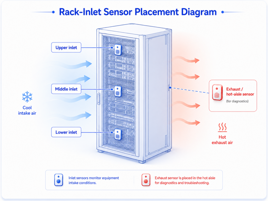
    Rack-inlet sensor placement diagram

    For a small server room, a practical starting point is one sensor at the front of the most critical rack, one room-level sensor away from direct supply air, and a water-leak sensor near the most likely source. Larger rooms should divide the space by rack row, cooling zone, containment section, or load density. The number of sensors should be based on observed thermal variation and business risk rather than a fixed square-metre rule.

    A high-density rack can develop a vertical temperature gradient. Measuring near the lower, middle, and upper rack inlets makes it easier to identify insufficient airflow at the top of the cabinet. In lower-density rows, selected representative racks may be enough, provided the layout has been checked through temporary mapping or commissioning measurements. When loads change significantly, the mapping should be repeated or the permanent sensor layout should be expanded.

    Hot-aisle or return-air sensors provide diagnostic information. They help the facilities team assess heat removal, containment leakage, and cooling-unit performance, but they should not be used as the only basis for server inlet alarms. Sensors near supply outlets can also support troubleshooting, although a probe placed directly in a cold-air jet may understate the temperature reaching equipment farther along the aisle.

    Moisture monitoring should follow the physical path of a possible leak. Rope or spot-leak sensors may be placed near cooling units, condensate lines, humidifiers, chilled-water pipes, liquid-cooling distribution units, under raised floors, and at low points where water can collect. A leak detector in the centre of a room may never encounter water from a pipe that drains toward a wall.
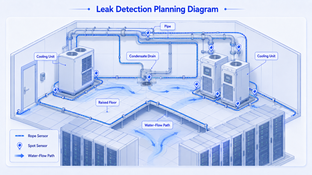
    Leak Detection Planning Diagram

    Avoid mounting temperature and humidity sensors against outside walls, near doors, directly above equipment exhausts, inside a strong supply-air stream, or where technicians can block them with tools or temporary cabling. Keep sensor labels visible and protect probe cables from sharp bends, rack-door hinges, and accidental disconnection.

    Select Devices, Probes, and Communications for the Site

    The monitoring device must match the measurement point, network policy, expansion plan, and expected response time. A compact Ethernet temperature sensor may be sufficient for one server room, while a large colocation site may require rack appliances, hundreds of external probes, access control, SNMP, DCIM integration, and redundant management paths.

    For a straightforward Ethernet or WiFi deployment, the UbiBot GS1-AETH1RS combines an internal temperature and humidity sensor with local storage, cloud connectivity, and external RS485-compatible probe support. The published internal measurement range is -20°C to 60°C for temperature and 10% to 90% RH, non-condensing, with stated accuracy of ±0.2°C and ±2% RH. It stores up to 300,000 sensor records and connects through RJ45 Ethernet or 2.4 GHz WiFi. Power options include an internal lithium battery, Type-C USB, DC input, and an optional PoE splitter.[4][5]

    The internal battery is useful as short-term backup, but a permanent data center installation should normally use a managed power source. The device can be positioned at room or rack level, while external probes allow the display and network unit to remain accessible. RS485 on this model is used for compatible external probes; it should not be confused with the Ethernet path used to upload data to the platform.

    Ethernet is usually the preferred primary connection in controlled data center environments because it is stable, easier to segment, and compatible with network-management policies. WiFi can reduce cabling in a retrofit, but metal racks, containment panels, and channel congestion must be tested under real operating conditions. Cellular communication can provide an independent path for edge sites or temporary deployment, but it requires signal testing, SIM management, and a clear policy on whether the connection is primary or backup.

    LoRa or proprietary long-range wireless systems are useful when many battery-powered sensors report to one gateway. They can lower cabling requirements across a large white space, but the gateway becomes a shared dependency. RS485 is effective for fixed probes and building systems where cable routes are available, especially when the monitoring architecture already includes Modbus devices. The trade-off is additional design work around addressing, topology, termination, cable segregation, and gateway capacity.

    Accuracy should be evaluated against the operational decision. A rack-inlet alarm does not always need laboratory-grade accuracy, but the sensor must be stable, traceable where required, and consistent across the installed fleet. Resolution should not be presented as accuracy. A device can display small increments while still having a wider measurement uncertainty.

    Install the Hardware and Connect the Network

    A consistent installation method makes data easier to compare across racks and sites. The device ID in the platform, the physical label, the floor plan, and the maintenance record should all refer to the same location.

    Use a naming convention that remains readable when the estate grows. A practical format is:

    Recommended device name

    Site – Room – Row – Rack – Position – Parameter
    Example: LON1 – Hall B – Row 07 – Rack 24 – Front Upper – Temp/RH

    Mount rack-inlet probes on the cold side of the cabinet without blocking airflow or preventing door access. Where a rack has upper, middle, and lower probes, use the same heights across comparable cabinets. Secure the cable with removable management points rather than routing it across fan modules, power connectors, or service panels. For room-level devices, choose a position that represents the occupied equipment zone rather than the ceiling or a convenient office wall.

    Before connecting a device to the production network, confirm the approved VLAN, addressing method, DNS, NTP, proxy requirements, and outbound ports. If the platform is cloud-hosted, test connectivity through the actual firewall path. If the organization requires local or on-premises management, confirm server capacity, backup, certificate management, and responsibility for software updates before devices are installed.

    Ethernet deployments should use labelled switch ports and documented cable paths. Optional PoE can simplify installation, but the specific device and splitter combination must be approved. The UbiBot GS1-AETH1RS product page lists optional PoE through a splitter, while Schneider Electric documents the NetBotz Rack Monitor 250A as an AC-powered appliance rather than a PoE endpoint. AVTECH Room Alert 32S and AKCP sensorProbe2+ offer PoE options in their current configurations.[5]

    Where WiFi is used, test signal strength with rack doors and containment panels closed. Confirm that the SSID is 2.4 GHz if the selected device does not support 5 GHz. For RS485 probes, record the device address, baud rate, parity, cable type, termination, and maximum segment length. Keep low-voltage sensor cables separated from high-current conductors where practical, and follow local electrical and fire-safety requirements for cable routing.

    The installation should include a controlled loss-of-network test. Disconnect the uplink, confirm that local logging continues, restore communication, and verify that missing records are uploaded in the correct time sequence. A monitoring system that only works during a perfect network demonstration is not ready for an operational data center.

    Deploy the Cloud Platform, Alerts, and Integrations

    The platform should be configured around operational ownership. Device groups, thresholds, notification paths, permissions, reports, and integrations should mirror how the data center is managed.

    Start by creating a hierarchy such as region, campus, building, room, row, and rack. This allows the operations team to see local alarms without losing multi-site visibility. Create standard device templates for naming, sampling intervals, upload intervals, and alarm severity. A new site can then inherit controlled settings rather than being configured from memory.

    Thresholds should be based on the approved equipment envelope and local operating policy. The ASHRAE recommended range is a useful baseline, but the alarm limit does not need to equal the edge of the recommended range. A warning can be set earlier to provide response time, followed by a critical threshold that triggers escalation. Hysteresis and time delay are essential because rapid cooling cycles or short door-opening events can otherwise generate repeated alarms.

    A complete alarm design covers more than temperature and humidity. Add device-offline, sensor-error, low-battery, leak, power-loss, and communication alarms where supported. Define who receives each severity, how long acknowledgement can take, and when the alarm escalates to facilities, IT operations, or an on-call manager. During planned maintenance, use a documented suppression or maintenance mode rather than permanently widening thresholds.

    The UbiBot public IoT platform provides real-time and historical graphs, data export, customizable alerts, device sharing, data forwarding, and REST API access. Available notification channels and automated-report limits depend on the selected platform plan, so publication and procurement materials should distinguish free functions from paid services.[6]

    Integration requirements should be decided before the platform taxonomy is final. For DCIM or BMS integration, agree whether the external system will receive raw measurements, alarms, calculated values, or only selected critical points. Use stable device and sensor identifiers rather than display names that staff may edit. Test time zones, daylight-saving changes, units, missing-data handling, and API retry behaviour.
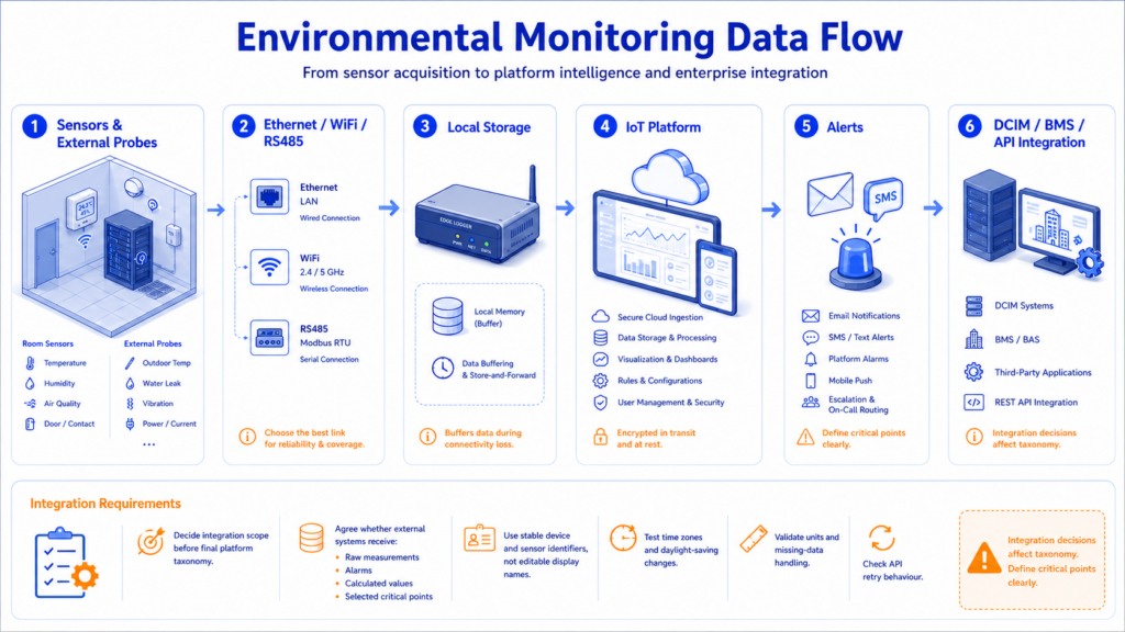
    Environmental monitoring data flow

    User permissions should follow least-privilege principles. A tenant or customer may need read-only access to selected racks, while a site engineer may need acknowledgement rights and a central administrator may control thresholds. Changes to alarm settings should be recorded and periodically reviewed, especially in colocation or regulated facilities.

    Commission, Validate, and Scale the Monitoring System

    Commissioning must prove the full chain from the physical sensor to the person expected to act. A plausible reading on a dashboard is not sufficient evidence that the system is correctly placed, connected, time-synchronized, and operational.
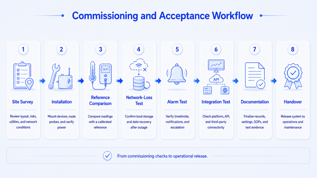
    Commissioning and Acceptance Workflow

    Compare each installed temperature and humidity sensor with a suitable reference instrument after it has stabilised. Record the device serial number, location, reference instrument, date, observed difference, and acceptance result. This field comparison is not a substitute for formal calibration, but it can detect swapped labels, damaged probes, incorrect units, or major offsets.

    Next, test the alarm workflow. Raise the temperature around a test probe or temporarily use a controlled threshold that can be crossed safely. Confirm the warning, critical alarm, notification, acknowledgement, escalation, and event record. Test device-offline and leak alarms separately. Restore the normal threshold under change control after the test.

    Network resilience testing should cover LAN interruption, WAN interruption, platform unavailability, and power loss where practical. Verify local storage and automatic backfill, and confirm that reports show the original measurement time rather than the later upload time. For systems integrated with DCIM, BMS, SNMP, MQTT, or an API, compare the source reading with the downstream value and alarm state.

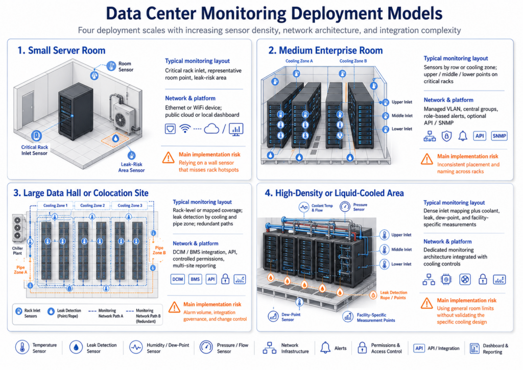
    Scaling changes the architecture. The table below gives a planning reference rather than a fixed sensor-count rule.

    Deployment scale Typical monitoring layout Network and platform approach Main implementation risk
    Small server room Critical rack inlet, representative room point, and leak risk area Ethernet or WiFi device; public cloud or local dashboard Relying on a wall sensor that misses rack hotspots
    Medium enterprise room Sensors by row or cooling zone; upper/middle/lower points on selected critical racks Managed VLAN, central groups, role-based alerts, optional API/SNMP Inconsistent placement and naming across racks
    Large data hall or colocation site Rack-level or mapped coverage, leak detection by cooling and pipe zone, redundant monitoring paths DCIM/BMS integration, API, controlled permissions, multi-site reporting Alarm volume, integration governance, and change control
    High-density or liquid-cooled area Dense inlet mapping plus coolant, leak, dew-point, and facility-specific measurements Dedicated monitoring architecture integrated with cooling controls Using general room limits without validating the specific cooling design

    Small, medium, and large data center deployment

    After acceptance, create a maintenance schedule for calibration or verification, probe inspection, battery health, firmware, network certificates, alarm contacts, and platform permissions. Review sensor coverage after rack moves, major load changes, containment modifications, cooling upgrades, or repeated unexplained alarms. Monitoring is part of the operating environment and should change when the environment changes.

    Comparison of Current Data Center Monitoring Devices

    The products below represent different deployment routes: a compact cloud-connected Ethernet monitor, a rack appliance with large sensor expansion, a multi-port facility monitor, and an IP sensor gateway. For a current-market comparison, the table uses Schneider Electric NetBotz Rack Monitor 250A, AVTECH Room Alert 32S, and AKCP sensorProbe2+. Their earlier counterparts – NetBotz 250, Room Alert 32E, and sensorProbe8 – are legacy or discontinued models.

    The UbiBot GS1-AETH1RS is the simplest of the four architectures when the project needs a compact Ethernet or WiFi device with internal logging and cloud management. It can be deployed without a separate rack controller and can add compatible external probes. Its expansion scale is smaller than the dedicated rack appliances, so large data halls should evaluate the required number of channels and the platform architecture before standardising on one unit per rack or zone.

    The NetBotz 250A is designed for deeper integration into a professional data center environment. Its high sensor capacity, rack-access functions, and EcoStruxure ecosystem are valuable where those capabilities are required. The trade-off is a more specialised architecture and a larger implementation scope than a compact cloud monitor.

    Room Alert 32S provides many wired inputs and dry contacts in one rack unit, which is useful for server rooms that need to combine temperature, humidity, leak, power, door, and third-party switch signals. Its internal temperature and humidity accuracy is less precise than the stated internal specification of the UbiBot GS1-AETH1RS, so the comparison should focus on the complete facility-monitoring architecture rather than a single sensor value.

    AKCP sensorProbe2+ is a modular IP gateway with broad protocol support. It fits small data centers and individual cabinets that need intelligent sensors, SNMP, MQTT, BACnet, or optional Modbus. Its port licensing and configuration options should be included in project costing.

    Product Comparison: Data Center Environmental Monitoring

    Comparison item UbiBot GS1-AETH1RS Schneider Electric NetBotz 250A + AP9335TH AVTECH Room Alert 32S AKCP sensorProbe2+ + THS01
    Deployment model Compact cloud-connected monitor with internal sensors and external RS485 probe expansion Rack appliance for environmental sensing, access control, and large sensor expansion 1U facility monitor with internal sensors and multiple digital, switch, analog, and relay ports Compact IP gateway for intelligent sensors and dry contacts
    Temperature range and accuracy -20°C to 60°C; ±0.2°C AP9335TH current product page confirms T/RH measurement; exact range and accuracy should be taken from the current regional guide/data sheet -40°C to 85°C; ±2°C THS01: -55°C to 75°C; ±0.5°C from -10°C to 75°C
    Humidity range and accuracy 10% to 90% RH, non-condensing; ±2% RH Not publicly specified on the current product page; verify the current guide for the selected sensor revision 5% to 85% RH internal sensor; ±4.5% RH at 5-59% RH and ±6.5% RH at 60-95% RH THS01: 0% to 100% RH; ±2% to ±5% RH at 25°C
    Primary network RJ45 Ethernet or 2.4 GHz WiFi 10/100 Ethernet through NMC3 RJ45 Ethernet Ethernet; optional cellular modem
    Protocols and integration UbiBot cloud, REST API, data forwarding; RS485-compatible external probes HTTPS, SNMP, Modbus and EcoStruxure/DCIM integration Built-in web interface, RoomAlert.com, SNMP, HTTP/JSON and compatible management software SNMPv1/v2c/v3, HTTPS, MQTT, BACnet, Modbus TCP; optional RS485 on SP2+E
    Sensor expansion Up to 33 external compatible probes; multiple RS485 probes supported with splitters, subject to model rules Up to 42 wired sensors and 47 wireless sensors; rack-door access support 8 digital, 16 switch, 2 analog, 2 relay, and 2 light-tower/relay adapter ports Up to 4 intelligent sensors; 2 ports enabled by default, up to 20 dry contacts
    Local storage Up to 300,000 sensor records Onboard logs supported; exact public capacity not specified Exact public capacity not specified Exact public capacity not specified
    Power Internal lithium battery; Type-C USB; DC input; optional PoE splitter AC-powered rack appliance; not a PoE endpoint 5V adapter or IEEE 802.3af PoE 5V DC, 3A; optional IEEE 802.3af PoE
    Platform and alerts Real-time and historical data, threshold alerts, exports, sharing, reports, API and data forwarding, plan-dependent functions Environmental alerts with EcoStruxure IT and NetBotz management ecosystem Room Alert web interface and account services; email/SMS/platform features depend on configuration and plan Web interface, encrypted traps/email, graphing, AKCP.ro Server and optional licensed features
    Best-fit deployment Server rooms and distributed sites needing fast Ethernet/WiFi deployment, cloud access, local storage, and flexible probe expansion Data centers needing extensive sensor scaling, access control, and Schneider Electric ecosystem integration Facilities needing many hardwired sensor and dry-contact inputs in one rack unit Small data centers, server rooms, cabinets, and expandable IP sensor deployments

    Frequently Asked Questions

    Where should temperature sensors be placed in a data center?

    Place the primary sensors at the air inlets of critical IT equipment. Add room, hot-aisle, return-air, and supply-air measurements for context and troubleshooting. High-density racks may need lower, middle, and upper inlet sensors.

    How many temperature sensors does a server room need?

    There is no universal number. A small room may begin with a critical rack-inlet point, a representative room point, and leak detection. Larger rooms should be divided by rack row, cooling zone, containment section, and load density, then validated through mapping or commissioning measurements.

    What temperature should trigger a rack alert?

    Use the approved operating envelope for the installed IT equipment and the site cooling policy. The ASHRAE recommended range is a planning reference, but warning and critical thresholds should provide enough time for intervention and should include suitable delay and hysteresis.

    Is a room temperature sensor enough for a data center?

    No. A room sensor can miss local rack hotspots and vertical gradients. It is useful for context, but critical alarms should be based on representative equipment-inlet measurements.

    Should data center sensors use Ethernet, WiFi, or RS485?

    Ethernet is usually preferred for stable, managed connectivity. WiFi can speed retrofit deployment but needs coverage testing around metal racks and containment. RS485 is effective for fixed external probes and Modbus systems where cabling and topology can be controlled.

    What happens if the monitoring network goes offline?

    The monitoring device should continue recording locally and upload missing records after communication returns. The installation team should test this behaviour and confirm that original timestamps are preserved.

    How often should data center temperature and humidity sensors be calibrated?

    The interval should follow the organization’s quality policy, manufacturer guidance, risk level, and any customer or regulatory requirements. At minimum, establish a documented periodic verification process and recheck sensors after damage, repair, relocation, or unexplained drift.

    Can environmental monitoring data be integrated with DCIM or BMS software?

    Yes, when the device or platform supports suitable APIs or protocols such as REST, SNMP, MQTT, BACnet, Modbus, or data forwarding. The integration should be tested for units, timestamps, alarm states, missing data, authentication, and retry behaviour.

    A successful data center environment monitoring deployment is built around representative rack-inlet measurements, documented sensor positions, reliable network and local storage behaviour, controlled alarms, and a tested response process. The UbiBot GS1-AETH1RS is a practical option for server rooms and distributed sites that need Ethernet or WiFi connectivity, cloud-based visibility, local data storage, and external probe support without deploying a larger rack appliance. Sites requiring extensive access control, dozens of sensor channels, or an established DCIM ecosystem should evaluate the dedicated rack-monitoring architectures alongside it.

    Product and Standards Sources

    [1] ASHRAE Handbook – Data Centers and Telecommunications Facilities

    [2] ISO/IEC 22237-4:2021 – Data centre facilities and infrastructures: Environmental control

    [3] TIA-942-C Data Center Infrastructure Standard

    [4] UbiBot GS1-AETH1RS Specifications

    [5] UbiBot GS1-AETH1RS Product Page

    [6] UbiBot Public IoT Platform

    Related Resources

    No related resources found

    menu-header-svg
    Search
    • Explore Knowledge
      • Industry Solution
      • Product & Device
      • Technology & Principle
      • Deployment & Usage
      • Criterion & Compliance
      • Comparison & Selection
    • Academic Research
    • In-depth Tech

    learn

    See More >>

    Data Center Environment Monitoring Deployment Guide

    Key Takeaway

    This guide begins after the organization has decided to install an environmental monitoring system. It concentrates on implementation: where to measure, how to connect devices, how to configure alarms and integrations, and how to prove that the completed system works.

    Introduction

    A data center temperature monitor is only useful when it measures the conditions that IT equipment actually experiences. A sensor mounted on a wall may show a stable room temperature while the upper inlet of a high-density rack is already overheating. In the same way, a dashboard can look complete while a network failure, incorrect alarm delay, or poor device naming prevents the operations team from responding quickly.

    Most deployment problems come from four decisions made too early: using room averages instead of rack-inlet measurements, placing too few sensors in thermally different areas, relying on one communication path without testing failure behaviour, and configuring alerts before responsibilities and escalation rules have been agreed. A practical deployment should connect the physical layout, cooling design, sensor architecture, network, cloud platform, and operating procedure as one system.

    ASHRAE uses IT equipment inlet conditions as the central reference for air-cooled data center environments. The widely used recommended dry-bulb range for Classes A1 to A4 is 18°C to 27°C, but the approved operating envelope for a specific site must still consider the installed equipment, local contamination risk, cooling strategy, and the current edition of the ASHRAE Thermal Guidelines. ISO/IEC 22237-4:2021 addresses temperature, humidity, fluid movement, particles, vibration, and the security of environmental control systems, while ANSI/TIA-942-C provides a broader infrastructure framework for data centers of different sizes.[1][2][3]

    Survey the Facility Before Selecting Monitoring Hardware

    The site survey should define where thermal and moisture risks can occur, how the sensors will communicate, and which operational team will own each alarm. Device selection should follow this survey, not replace it.

    Begin with the room and cooling layout. Record rack rows, hot aisles, cold aisles, containment boundaries, computer room air-conditioning or air-handling units, raised-floor supply tiles, overhead ducts, return-air paths, blanking-panel gaps, cable openings, and any liquid-cooling distribution equipment. Note the design airflow direction and compare it with observed airflow. A rack located near a missing floor tile or a poorly sealed cable opening may behave differently from the rest of the row even when the room average is normal.

    The survey should also identify critical loads. High-density AI or GPU racks, storage arrays, network cores, and racks with limited airflow deserve more granular monitoring than lightly loaded cabinets. For a colocation facility, the monitoring boundary must be agreed with tenants: the operator may monitor the white space and rack fronts, while a customer may require dedicated sensors inside a cage or cabinet.

    Network and power conditions should be documented at the same time. Confirm the availability of 2.4 GHz WiFi, Ethernet switch ports, VLANs, firewall rules, Power over Ethernet, local DC power, and cellular coverage for backup or remote sites. Where a device will use Ethernet, agree whether it will sit on the building-management network, the DCIM network, a dedicated monitoring VLAN, or an isolated customer network. The design should state how data will be retained if the cloud, LAN, or WAN becomes unavailable.

    The final survey item is the operating process. Identify who can change thresholds, who receives first-line alerts, who investigates a rack-temperature excursion, and who closes the incident. Monitoring projects often fail operationally because several people receive the same message but nobody owns the response.

    A useful survey output

    Create one annotated floor plan showing rack rows, cooling units, containment, water sources, network points, power sources, proposed sensor IDs, and the alarm owner for each zone. This becomes the reference for installation, commissioning, maintenance, and future expansion.

    Place Sensors at Rack Inlets and Failure-Prone Zones

    Rack-inlet temperature is the primary measurement for air-cooled IT equipment because it shows the air entering the servers. Room-level sensors are still useful for context, but they should not be treated as a substitute for measurements at critical rack fronts.

    Rack-inlet sensor placement diagram

    For a small server room, a practical starting point is one sensor at the front of the most critical rack, one room-level sensor away from direct supply air, and a water-leak sensor near the most likely source. Larger rooms should divide the space by rack row, cooling zone, containment section, or load density. The number of sensors should be based on observed thermal variation and business risk rather than a fixed square-metre rule.

    A high-density rack can develop a vertical temperature gradient. Measuring near the lower, middle, and upper rack inlets makes it easier to identify insufficient airflow at the top of the cabinet. In lower-density rows, selected representative racks may be enough, provided the layout has been checked through temporary mapping or commissioning measurements. When loads change significantly, the mapping should be repeated or the permanent sensor layout should be expanded.

    Hot-aisle or return-air sensors provide diagnostic information. They help the facilities team assess heat removal, containment leakage, and cooling-unit performance, but they should not be used as the only basis for server inlet alarms. Sensors near supply outlets can also support troubleshooting, although a probe placed directly in a cold-air jet may understate the temperature reaching equipment farther along the aisle.

    Moisture monitoring should follow the physical path of a possible leak. Rope or spot-leak sensors may be placed near cooling units, condensate lines, humidifiers, chilled-water pipes, liquid-cooling distribution units, under raised floors, and at low points where water can collect. A leak detector in the centre of a room may never encounter water from a pipe that drains toward a wall.

    Leak Detection Planning Diagram

    Avoid mounting temperature and humidity sensors against outside walls, near doors, directly above equipment exhausts, inside a strong supply-air stream, or where technicians can block them with tools or temporary cabling. Keep sensor labels visible and protect probe cables from sharp bends, rack-door hinges, and accidental disconnection.

    Select Devices, Probes, and Communications for the Site

    The monitoring device must match the measurement point, network policy, expansion plan, and expected response time. A compact Ethernet temperature sensor may be sufficient for one server room, while a large colocation site may require rack appliances, hundreds of external probes, access control, SNMP, DCIM integration, and redundant management paths.

    For a straightforward Ethernet or WiFi deployment, the UbiBot GS1-AETH1RS combines an internal temperature and humidity sensor with local storage, cloud connectivity, and external RS485-compatible probe support. The published internal measurement range is -20°C to 60°C for temperature and 10% to 90% RH, non-condensing, with stated accuracy of ±0.2°C and ±2% RH. It stores up to 300,000 sensor records and connects through RJ45 Ethernet or 2.4 GHz WiFi. Power options include an internal lithium battery, Type-C USB, DC input, and an optional PoE splitter.[4][5]

    The internal battery is useful as short-term backup, but a permanent data center installation should normally use a managed power source. The device can be positioned at room or rack level, while external probes allow the display and network unit to remain accessible. RS485 on this model is used for compatible external probes; it should not be confused with the Ethernet path used to upload data to the platform.

    Ethernet is usually the preferred primary connection in controlled data center environments because it is stable, easier to segment, and compatible with network-management policies. WiFi can reduce cabling in a retrofit, but metal racks, containment panels, and channel congestion must be tested under real operating conditions. Cellular communication can provide an independent path for edge sites or temporary deployment, but it requires signal testing, SIM management, and a clear policy on whether the connection is primary or backup.

    LoRa or proprietary long-range wireless systems are useful when many battery-powered sensors report to one gateway. They can lower cabling requirements across a large white space, but the gateway becomes a shared dependency. RS485 is effective for fixed probes and building systems where cable routes are available, especially when the monitoring architecture already includes Modbus devices. The trade-off is additional design work around addressing, topology, termination, cable segregation, and gateway capacity.

    Accuracy should be evaluated against the operational decision. A rack-inlet alarm does not always need laboratory-grade accuracy, but the sensor must be stable, traceable where required, and consistent across the installed fleet. Resolution should not be presented as accuracy. A device can display small increments while still having a wider measurement uncertainty.

    Install the Hardware and Connect the Network

    A consistent installation method makes data easier to compare across racks and sites. The device ID in the platform, the physical label, the floor plan, and the maintenance record should all refer to the same location.

    Use a naming convention that remains readable when the estate grows. A practical format is:

    Recommended device name

    Site – Room – Row – Rack – Position – Parameter
    Example: LON1 – Hall B – Row 07 – Rack 24 – Front Upper – Temp/RH

    Mount rack-inlet probes on the cold side of the cabinet without blocking airflow or preventing door access. Where a rack has upper, middle, and lower probes, use the same heights across comparable cabinets. Secure the cable with removable management points rather than routing it across fan modules, power connectors, or service panels. For room-level devices, choose a position that represents the occupied equipment zone rather than the ceiling or a convenient office wall.

    Before connecting a device to the production network, confirm the approved VLAN, addressing method, DNS, NTP, proxy requirements, and outbound ports. If the platform is cloud-hosted, test connectivity through the actual firewall path. If the organization requires local or on-premises management, confirm server capacity, backup, certificate management, and responsibility for software updates before devices are installed.

    Ethernet deployments should use labelled switch ports and documented cable paths. Optional PoE can simplify installation, but the specific device and splitter combination must be approved. The UbiBot GS1-AETH1RS product page lists optional PoE through a splitter, while Schneider Electric documents the NetBotz Rack Monitor 250A as an AC-powered appliance rather than a PoE endpoint. AVTECH Room Alert 32S and AKCP sensorProbe2+ offer PoE options in their current configurations.[5]

    Where WiFi is used, test signal strength with rack doors and containment panels closed. Confirm that the SSID is 2.4 GHz if the selected device does not support 5 GHz. For RS485 probes, record the device address, baud rate, parity, cable type, termination, and maximum segment length. Keep low-voltage sensor cables separated from high-current conductors where practical, and follow local electrical and fire-safety requirements for cable routing.

    The installation should include a controlled loss-of-network test. Disconnect the uplink, confirm that local logging continues, restore communication, and verify that missing records are uploaded in the correct time sequence. A monitoring system that only works during a perfect network demonstration is not ready for an operational data center.

    Deploy the Cloud Platform, Alerts, and Integrations

    The platform should be configured around operational ownership. Device groups, thresholds, notification paths, permissions, reports, and integrations should mirror how the data center is managed.

    Start by creating a hierarchy such as region, campus, building, room, row, and rack. This allows the operations team to see local alarms without losing multi-site visibility. Create standard device templates for naming, sampling intervals, upload intervals, and alarm severity. A new site can then inherit controlled settings rather than being configured from memory.

    Thresholds should be based on the approved equipment envelope and local operating policy. The ASHRAE recommended range is a useful baseline, but the alarm limit does not need to equal the edge of the recommended range. A warning can be set earlier to provide response time, followed by a critical threshold that triggers escalation. Hysteresis and time delay are essential because rapid cooling cycles or short door-opening events can otherwise generate repeated alarms.

    A complete alarm design covers more than temperature and humidity. Add device-offline, sensor-error, low-battery, leak, power-loss, and communication alarms where supported. Define who receives each severity, how long acknowledgement can take, and when the alarm escalates to facilities, IT operations, or an on-call manager. During planned maintenance, use a documented suppression or maintenance mode rather than permanently widening thresholds.

    The UbiBot public IoT platform provides real-time and historical graphs, data export, customizable alerts, device sharing, data forwarding, and REST API access. Available notification channels and automated-report limits depend on the selected platform plan, so publication and procurement materials should distinguish free functions from paid services.[6]

    Integration requirements should be decided before the platform taxonomy is final. For DCIM or BMS integration, agree whether the external system will receive raw measurements, alarms, calculated values, or only selected critical points. Use stable device and sensor identifiers rather than display names that staff may edit. Test time zones, daylight-saving changes, units, missing-data handling, and API retry behaviour.

    Environmental monitoring data flow

    User permissions should follow least-privilege principles. A tenant or customer may need read-only access to selected racks, while a site engineer may need acknowledgement rights and a central administrator may control thresholds. Changes to alarm settings should be recorded and periodically reviewed, especially in colocation or regulated facilities.

    Commission, Validate, and Scale the Monitoring System

    Commissioning must prove the full chain from the physical sensor to the person expected to act. A plausible reading on a dashboard is not sufficient evidence that the system is correctly placed, connected, time-synchronized, and operational.

    Commissioning and Acceptance Workflow

    Compare each installed temperature and humidity sensor with a suitable reference instrument after it has stabilised. Record the device serial number, location, reference instrument, date, observed difference, and acceptance result. This field comparison is not a substitute for formal calibration, but it can detect swapped labels, damaged probes, incorrect units, or major offsets.

    Next, test the alarm workflow. Raise the temperature around a test probe or temporarily use a controlled threshold that can be crossed safely. Confirm the warning, critical alarm, notification, acknowledgement, escalation, and event record. Test device-offline and leak alarms separately. Restore the normal threshold under change control after the test.

    Network resilience testing should cover LAN interruption, WAN interruption, platform unavailability, and power loss where practical. Verify local storage and automatic backfill, and confirm that reports show the original measurement time rather than the later upload time. For systems integrated with DCIM, BMS, SNMP, MQTT, or an API, compare the source reading with the downstream value and alarm state.

    Scaling changes the architecture. The table below gives a planning reference rather than a fixed sensor-count rule.

    Deployment scale Typical monitoring layout Network and platform approach Main implementation risk
    Small server room Critical rack inlet, representative room point, and leak risk area Ethernet or WiFi device; public cloud or local dashboard Relying on a wall sensor that misses rack hotspots
    Medium enterprise room Sensors by row or cooling zone; upper/middle/lower points on selected critical racks Managed VLAN, central groups, role-based alerts, optional API/SNMP Inconsistent placement and naming across racks
    Large data hall or colocation site Rack-level or mapped coverage, leak detection by cooling and pipe zone, redundant monitoring paths DCIM/BMS integration, API, controlled permissions, multi-site reporting Alarm volume, integration governance, and change control
    High-density or liquid-cooled area Dense inlet mapping plus coolant, leak, dew-point, and facility-specific measurements Dedicated monitoring architecture integrated with cooling controls Using general room limits without validating the specific cooling design

    Small, medium, and large data center deployment

    After acceptance, create a maintenance schedule for calibration or verification, probe inspection, battery health, firmware, network certificates, alarm contacts, and platform permissions. Review sensor coverage after rack moves, major load changes, containment modifications, cooling upgrades, or repeated unexplained alarms. Monitoring is part of the operating environment and should change when the environment changes.

    Comparison of Current Data Center Monitoring Devices

    The products below represent different deployment routes: a compact cloud-connected Ethernet monitor, a rack appliance with large sensor expansion, a multi-port facility monitor, and an IP sensor gateway. For a current-market comparison, the table uses Schneider Electric NetBotz Rack Monitor 250A, AVTECH Room Alert 32S, and AKCP sensorProbe2+. Their earlier counterparts – NetBotz 250, Room Alert 32E, and sensorProbe8 – are legacy or discontinued models.

    The UbiBot GS1-AETH1RS is the simplest of the four architectures when the project needs a compact Ethernet or WiFi device with internal logging and cloud management. It can be deployed without a separate rack controller and can add compatible external probes. Its expansion scale is smaller than the dedicated rack appliances, so large data halls should evaluate the required number of channels and the platform architecture before standardising on one unit per rack or zone.

    The NetBotz 250A is designed for deeper integration into a professional data center environment. Its high sensor capacity, rack-access functions, and EcoStruxure ecosystem are valuable where those capabilities are required. The trade-off is a more specialised architecture and a larger implementation scope than a compact cloud monitor.

    Room Alert 32S provides many wired inputs and dry contacts in one rack unit, which is useful for server rooms that need to combine temperature, humidity, leak, power, door, and third-party switch signals. Its internal temperature and humidity accuracy is less precise than the stated internal specification of the UbiBot GS1-AETH1RS, so the comparison should focus on the complete facility-monitoring architecture rather than a single sensor value.

    AKCP sensorProbe2+ is a modular IP gateway with broad protocol support. It fits small data centers and individual cabinets that need intelligent sensors, SNMP, MQTT, BACnet, or optional Modbus. Its port licensing and configuration options should be included in project costing.

    Product Comparison: Data Center Environmental Monitoring

    Comparison item UbiBot GS1-AETH1RS Schneider Electric NetBotz 250A + AP9335TH AVTECH Room Alert 32S AKCP sensorProbe2+ + THS01
    Deployment model Compact cloud-connected monitor with internal sensors and external RS485 probe expansion Rack appliance for environmental sensing, access control, and large sensor expansion 1U facility monitor with internal sensors and multiple digital, switch, analog, and relay ports Compact IP gateway for intelligent sensors and dry contacts
    Temperature range and accuracy -20°C to 60°C; ±0.2°C AP9335TH current product page confirms T/RH measurement; exact range and accuracy should be taken from the current regional guide/data sheet -40°C to 85°C; ±2°C THS01: -55°C to 75°C; ±0.5°C from -10°C to 75°C
    Humidity range and accuracy 10% to 90% RH, non-condensing; ±2% RH Not publicly specified on the current product page; verify the current guide for the selected sensor revision 5% to 85% RH internal sensor; ±4.5% RH at 5-59% RH and ±6.5% RH at 60-95% RH THS01: 0% to 100% RH; ±2% to ±5% RH at 25°C
    Primary network RJ45 Ethernet or 2.4 GHz WiFi 10/100 Ethernet through NMC3 RJ45 Ethernet Ethernet; optional cellular modem
    Protocols and integration UbiBot cloud, REST API, data forwarding; RS485-compatible external probes HTTPS, SNMP, Modbus and EcoStruxure/DCIM integration Built-in web interface, RoomAlert.com, SNMP, HTTP/JSON and compatible management software SNMPv1/v2c/v3, HTTPS, MQTT, BACnet, Modbus TCP; optional RS485 on SP2+E
    Sensor expansion Up to 33 external compatible probes; multiple RS485 probes supported with splitters, subject to model rules Up to 42 wired sensors and 47 wireless sensors; rack-door access support 8 digital, 16 switch, 2 analog, 2 relay, and 2 light-tower/relay adapter ports Up to 4 intelligent sensors; 2 ports enabled by default, up to 20 dry contacts
    Local storage Up to 300,000 sensor records Onboard logs supported; exact public capacity not specified Exact public capacity not specified Exact public capacity not specified
    Power Internal lithium battery; Type-C USB; DC input; optional PoE splitter AC-powered rack appliance; not a PoE endpoint 5V adapter or IEEE 802.3af PoE 5V DC, 3A; optional IEEE 802.3af PoE
    Platform and alerts Real-time and historical data, threshold alerts, exports, sharing, reports, API and data forwarding, plan-dependent functions Environmental alerts with EcoStruxure IT and NetBotz management ecosystem Room Alert web interface and account services; email/SMS/platform features depend on configuration and plan Web interface, encrypted traps/email, graphing, AKCP.ro Server and optional licensed features
    Best-fit deployment Server rooms and distributed sites needing fast Ethernet/WiFi deployment, cloud access, local storage, and flexible probe expansion Data centers needing extensive sensor scaling, access control, and Schneider Electric ecosystem integration Facilities needing many hardwired sensor and dry-contact inputs in one rack unit Small data centers, server rooms, cabinets, and expandable IP sensor deployments

    Frequently Asked Questions

    Where should temperature sensors be placed in a data center?

    Place the primary sensors at the air inlets of critical IT equipment. Add room, hot-aisle, return-air, and supply-air measurements for context and troubleshooting. High-density racks may need lower, middle, and upper inlet sensors.

    How many temperature sensors does a server room need?

    There is no universal number. A small room may begin with a critical rack-inlet point, a representative room point, and leak detection. Larger rooms should be divided by rack row, cooling zone, containment section, and load density, then validated through mapping or commissioning measurements.

    What temperature should trigger a rack alert?

    Use the approved operating envelope for the installed IT equipment and the site cooling policy. The ASHRAE recommended range is a planning reference, but warning and critical thresholds should provide enough time for intervention and should include suitable delay and hysteresis.

    Is a room temperature sensor enough for a data center?

    No. A room sensor can miss local rack hotspots and vertical gradients. It is useful for context, but critical alarms should be based on representative equipment-inlet measurements.

    Should data center sensors use Ethernet, WiFi, or RS485?

    Ethernet is usually preferred for stable, managed connectivity. WiFi can speed retrofit deployment but needs coverage testing around metal racks and containment. RS485 is effective for fixed external probes and Modbus systems where cabling and topology can be controlled.

    What happens if the monitoring network goes offline?

    The monitoring device should continue recording locally and upload missing records after communication returns. The installation team should test this behaviour and confirm that original timestamps are preserved.

    How often should data center temperature and humidity sensors be calibrated?

    The interval should follow the organization’s quality policy, manufacturer guidance, risk level, and any customer or regulatory requirements. At minimum, establish a documented periodic verification process and recheck sensors after damage, repair, relocation, or unexplained drift.

    Can environmental monitoring data be integrated with DCIM or BMS software?

    Yes, when the device or platform supports suitable APIs or protocols such as REST, SNMP, MQTT, BACnet, Modbus, or data forwarding. The integration should be tested for units, timestamps, alarm states, missing data, authentication, and retry behaviour.

    A successful data center environment monitoring deployment is built around representative rack-inlet measurements, documented sensor positions, reliable network and local storage behaviour, controlled alarms, and a tested response process. The UbiBot GS1-AETH1RS is a practical option for server rooms and distributed sites that need Ethernet or WiFi connectivity, cloud-based visibility, local data storage, and external probe support without deploying a larger rack appliance. Sites requiring extensive access control, dozens of sensor channels, or an established DCIM ecosystem should evaluate the dedicated rack-monitoring architectures alongside it.

    Product and Standards Sources

    [1] ASHRAE Handbook – Data Centers and Telecommunications Facilities

    [2] ISO/IEC 22237-4:2021 – Data centre facilities and infrastructures: Environmental control

    [3] TIA-942-C Data Center Infrastructure Standard

    [4] UbiBot GS1-AETH1RS Specifications

    [5] UbiBot GS1-AETH1RS Product Page

    [6] UbiBot Public IoT Platform

    分享

    LinkedIn2

    Facebook2

    X

    Newsletter Signup

    Related Resources

    No related resources found

    menu-header-svg
    Search
    • Explore Knowledge
      • Industry Solution
      • Product & Device
      • Technology & Principle
      • Deployment & Usage
      • Criterion & Compliance
      • Comparison & Selection
    • Academic Research
    • In-depth Tech
    Enter Your Information

    Confirm

    Products

    Dashboards

    Support

    Purchase

    Company

    Smart Sensing

    UbiBot Web Console

    APP Download

    UbiBot Online Store

    News

    Smart Control

    UbiBot Space

    Product Docs & APIs

    Find Distributors

    About Us

    Smart Video

    UbiBot On-Premises

    Helpdesk & FAQ

    Volume Pricing

    Contact Us

    LoRa Products

    Agency Web Console

    Video Center

    Architecture

    Software & Platform


    Pricing


    System Status

    External Sensors


    Become a Distributor

    Accessories


    Become an Affiliate

    Global SIM


    Positioning System


    Products

    Dashboards

    Business Partners

    WS1

    UbiBot Web Console

    Volume Pricing

    WS1 Pro

    UbiBot Space

    Become a Distributor

    GS1

    UbiBot Support Desk

    Affiliates

    GS2

    Agency Web Console


    MS1


    SP1


    Accessories


    Docs

    Purchase

    Company

    Platform API

    Pricing

    News

    Q&A

    UbiBot Partners

    About us

    Privacy Policy

    Online Store

    Contact

    Terms of Service


    System Status

    Products

    Dashboards

    Smart Sensing

    UbiBot Web Console

    Smart Control

    UbiBot Space

    Smart Video

    UbiBot On-Premises

    LoRa Products

    Agency Web Console

    Software & Platform


    External Sensors


    Accessories


    Global SIM


    Positioning System


    Support

    Purchase

    APP Download

    UbiBot Online Store

    Product Docs & APIs

    Find Distributors

    Helpdesk & FAQ

    Volume Pricing

    Video Center


    Pricing


    Company

    News

    About Us

    Contact Us

    Architecture

    System Status

    Become a Distributor

    Become an Affiliate

    Language:
    English 日本語 (ベータ)  
    Language:

    English

    日本語 (ベータ)


    IoT Product Family:
    ubibotico     Wireless environmental sensing products and smart building solutions
    ubitrackico     UWB-based real-time indoor tracking solutions with 30cm accuracy

    IoT Product Family:

    ubibotico  Wireless environmental sensing products and smart building solutions
    ubitrackico  UWB-based real-time indoor tracking solutions with 30cm accuracy

    © 2013-2026 UbiBot.com. All rights reserved.

    Terms of Service | Privacy Policy | Compliance

    youtube facebook twitter