

.svg)
Guide to Deploying a GxP Environmental Monitoring System in a Pharmaceutical Warehouse
Published: September 7, 2026
Update: September 8, 2026
By Jimmy Lianson
Key Takeaway
A GxP environmental monitoring system should be designed from documented storage requirements and temperature-mapping evidence. Sensor placement, alarms, electronic records, user access, calibration, backup, and validation must be controlled as one lifecycle process—not treated as separate hardware and software tasks.
A GxP environmental monitoring system in a pharmaceutical warehouse is not simply a set of temperature and humidity sensors connected to a dashboard. Once the project moves from business approval into deployment, the difficult questions become operational: which zones need independent monitoring, where permanent sensors should be installed after mapping, how alarms should be escalated, how records will remain available during network outages, and whether the configured system is suitable for the regulated use of its electronic records.
The first deployment mistake is to start with hardware. A warehouse may contain ambient storage, controlled-temperature rooms, quarantine stock, returns, receiving docks, dispatch areas, refrigerators, freezers, and high-bay racking, each with different environmental risks. A second mistake is to treat “GxP compliant” as a product feature. GxP suitability depends on the intended use of the complete system, the applicable GMP or GDP requirements, the configuration, validation evidence, procedures, security controls, calibration program, data governance, and change control.
For US drug-product warehousing, 21 CFR 211.142 requires written warehousing procedures and storage under appropriate temperature, humidity, and light conditions so product quality is not affected. In Europe, GDP guidance requires representative temperature mapping, risk-based placement of monitoring devices, calibration, alarm testing, and controls for computerised systems. WHO guidance likewise treats temperature mapping and continuous monitoring as integral to appropriate pharmaceutical storage. [1-5]
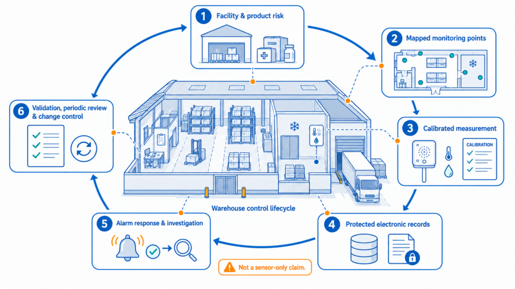
A GxP environmental monitoring system is a controlled lifecycle that connects facility risk, measurement, electronic records, alarm response, validation, and change control.
1. Define the GxP Monitoring Requirements Before Buying Hardware
Deployment should begin with a user requirements specification (URS) and a documented warehouse survey. The purpose is to translate product storage conditions, facility risks, IT constraints, and quality procedures into measurable system requirements before devices are selected.
Start by defining the storage regimes. Record the approved temperature range for each product family and identify whether relative humidity is a registered requirement, a packaging-protection requirement, or an investigative parameter. Separate ambient storage from refrigerated rooms, freezers, quarantine, returns, receiving, dispatch, sampling, and temporary staging. If one building stores several product classes, do not assume one set of alarm limits is appropriate for every zone.
The facility survey should document HVAC supply and return locations, racking height, mezzanines, external walls and roofs, solar exposure, loading doors, air curtains, refrigeration evaporators, defrost cycles, lighting, occupancy, forklift routes, and known areas of weak airflow. It should also identify practical installation constraints such as wash-down, condensation, forklift impact, cable routes, restricted ceiling spaces, and locations where stock could cover a sensor.
The IT and data survey is equally important. Confirm where Ethernet is available, whether WiFi is permitted on the operational network, whether VLAN or firewall rules apply, whether RS485 cabling is already installed, whether cloud services are approved, and whether an on-premises platform or API integration is required. Assign ownership for cybersecurity review, backups, account administration, and vendor access before installation begins.
The quality team must also decide what the records will be used for. If environmental data support deviation investigations, batch disposition, product-release decisions, or regulated electronic records, the required controls are more demanding than for a non-critical facility trend dashboard. FDA Part 11 applies to electronic records that fall within its scope; it is not a universal certification attached to every cloud application. EU GMP Annex 11 similarly expects lifecycle risk management, validated applications, qualified IT infrastructure, controlled access, data integrity, backup, audit trails where appropriate, and periodic review. [2,4]
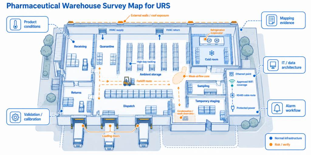
The URS should translate storage regimes, facility risks, IT constraints, record use, and quality procedures into measurable requirements before equipment is selected.
A practical URS for a pharmaceutical warehouse should define the following before procurement:
- Parameters to measure, approved ranges, required accuracy, and calibration traceability.
- Temperature-mapping requirements and the process for converting mapped hot/cold locations into permanent monitoring points.
- Measurement and upload intervals, local data retention during outages, record-retention periods, and time synchronization.
- High/low alarm logic, delay and hysteresis rules, escalation contacts, acknowledgement, and deviation handling.
- User roles, administrator privileges, password policy, change authorization, report access, and electronic-record controls.
- Network architecture, power/backup strategy, API or WMS/QMS/BMS integration, and recovery after network or platform failure.
- Validation deliverables, calibration records, maintenance schedule, periodic review, and change-control triggers.
2. Use Temperature Mapping to Define Permanent Monitoring Points
Permanent sensors should be installed from mapping evidence, not from a fixed rule such as one device per square metre. WHO defines temperature mapping as recording the temperature distribution within three-dimensional spaces, and EU GDP requires initial mapping under representative conditions before use, with monitoring equipment then located according to the mapping results. [3,5]
A mapping protocol should describe the warehouse configuration, logger positions, loading condition, study duration, measurement interval, seasonal condition, acceptance criteria, and operating events to be observed. The study should capture normal HVAC cycles, doors opening and closing, nights and weekends, defrost events, and changes in occupancy. Depending on the risk assessment, it may also include power interruption, restart, unusual loading, or a door-held-open challenge.
Mapping loggers should cover length, width, and the full storage height. High-bay racking can develop vertical stratification, while perimeter walls, roofs, dock doors, evaporators, supply-air jets, and weak-return zones can create repeatable extremes. A dense temporary mapping grid is therefore different from the final permanent monitoring network. The temporary study characterizes the space; the permanent network monitors the locations that matter after those patterns are understood.
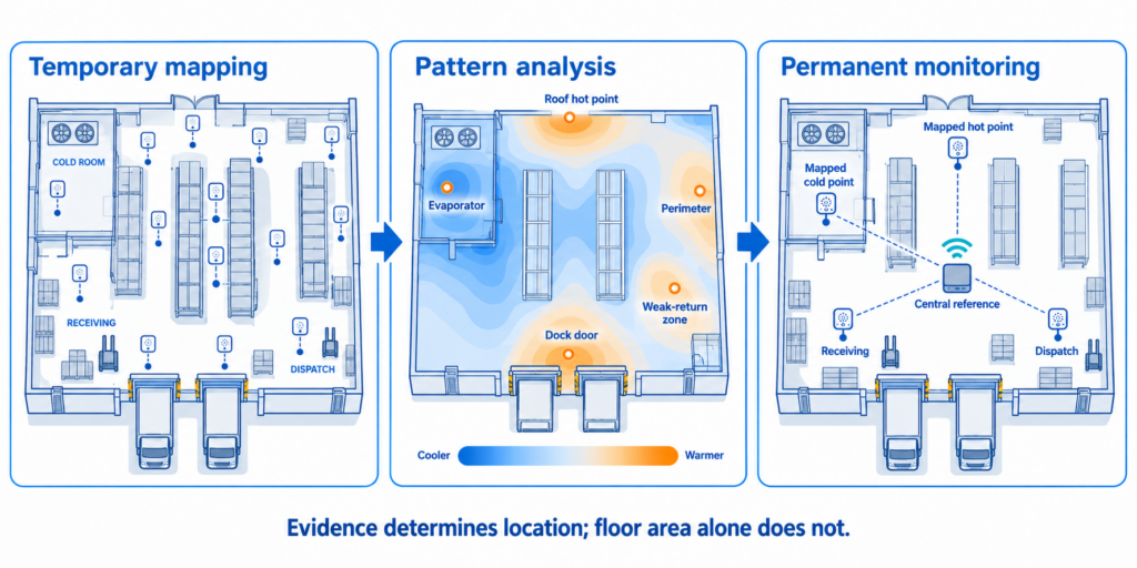
A dense temporary three-dimensional mapping grid reveals repeatable hot and cold patterns; the permanent network is then placed at mapped extremes and independently controlled zones.
After analysis, place permanent points at repeatable hot and cold locations and at zones that require independent operational control. A central “average” location can be retained as a representative reference, but it should not replace monitoring at mapped extremes. Receiving and dispatch areas may need separate points because they experience intentional exposure to outside air and may have different alarm logic from long-term storage.
Installation height should follow the mapped vertical gradient and the actual product-storage envelope. If products are stored from floor level to high racks, a sensor mounted only at eye level may not represent either extreme. Large spaces can require more than one permanent height; small rooms can justify fewer points only when mapping demonstrates uniformity.
Humidity should be treated in the same risk-based way. US CGMP language explicitly includes humidity among appropriate storage conditions, but not every pharmaceutical product has a formal RH release limit. Monitor and alarm humidity where product specifications, packaging, condensation risk, corrosion, mould prevention, HVAC control, or the quality risk assessment makes it relevant. Do not invent a GxP humidity limit simply because the sensor can measure RH. [1]
Avoid representative sensor positions that create an artificial microclimate: directly in a supply-air jet, against a hot external wall, in direct sunlight, above a heater, immediately beside a dock opening, on the floor, at the roof structure, or where cartons can block airflow. Those may be useful diagnostic locations when the risk itself is being monitored, but they should not be confused with representative product-storage conditions.
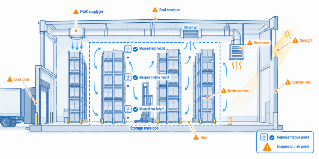
Permanent sensors should represent the mapped product-storage envelope; positions near direct air jets, sunlight, surfaces, doors, or blocked airflow should be used only when that specific risk is intentionally monitored.
3. Select Sensors, Probes, Connectivity, and Power as One Architecture
Device selection should follow the mapped range, required uncertainty, installation environment, network design, and record-use requirements. A highly accurate sensor is not enough if its data are lost during an outage, its calibration cannot be controlled, or its network architecture cannot be supported by the site.
For a fixed Ethernet/WiFi architecture, the UbiBot GS1-AETH1RS combines an internal temperature/humidity sensor, local display, local memory, Ethernet, WiFi, and support for selected RS485 external probes. Current UbiBot specifications list a built-in temperature range of -20°C to 60°C, humidity range of 10% to 90% RH non-condensing, stated accuracy of ±0.2°C and ±2% RH, and local memory for 300,000 sensor records. The device supports RJ45 Ethernet and 2.4 GHz WiFi, with Type-C/DC power and optional PoE on the current product page. [6]
External probes should be selected for the actual zone rather than added automatically. UbiBot lists the TH30S-B air temperature/humidity probe with a -40°C to 80°C and 0% to 100% RH measurement range, but the current public product page reviewed for this article does not publish a formal accuracy specification; the project should therefore obtain the current data sheet and calibration evidence before using that probe in a GxP-critical point. The UbiBot PT100 probe is specified for -200°C to 400°C and RS485/Modbus use, but its published accuracy and intended application should be assessed against the project uncertainty budget rather than assumed to be equivalent to a high-accuracy warehouse reference probe. [7,8]
Ethernet is normally the most predictable communications choice for fixed permanent warehouse points because it provides a controlled wired path and simplifies network troubleshooting. WiFi is useful for retrofits and hard-to-cable areas, but coverage should be tested with racks loaded and doors closed. RS485 is useful for external probes or integration into an existing BMS/PLC architecture; it requires controlled addressing, topology, shielding, termination, and cable documentation. Cellular or long-range radio architectures can add resilience or reduce cabling, but each additional gateway or carrier path becomes part of the validated signal chain.
Power should be designed for the required availability. Permanent warehouse monitoring points should normally use continuous protected power, with internal batteries treated as ride-through or short-term backup unless the device is explicitly designed for long-term battery operation. Test the complete outage path: sensor, gateway or switch, router/firewall, platform, and notification service. A backed-up sensor is of limited value if the switch or alarm route loses power at the same time.
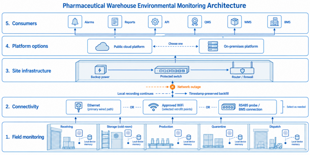
The monitoring architecture must preserve measurement, timestamps, communication, power, records, and notifications across the complete path—not only at the field sensor.
Calibration strategy belongs in device selection, not after installation. Define traceability requirements, calibration interval, acceptance tolerance, the process for as-found and as-left results, how failed calibration affects historical data, and whether a probe can be swapped without losing point identity. For regulated use, measurement uncertainty and calibration evidence can matter more than a small difference in headline resolution.
4. Install the Hardware and Configure the Platform Around Controlled Workflows
Installation should produce a repeatable physical and digital result at every monitoring point. Standard brackets, cable protection, labels, photographs, device names, and configuration templates make maintenance and audits easier than one-off installations.
Mount the sensing element where free air can circulate and where the position matches the approved mapping report. Protect external probe cables from forklifts, pallets, cleaning, and condensation. Use drip loops where moisture can travel along a cable. If a sensor is intentionally installed near a risk source, label it clearly as a diagnostic or risk point so that users do not interpret it as the warehouse average.
For Ethernet installations, assign the switch port, network segment, IP method, DNS requirements, outbound communication rules, and cybersecurity approvals before the installer arrives. If WiFi is used, document the approved SSID, security method, coverage evidence, and fallback behavior. For RS485 probes, record the device address, baud rate, cable route, termination, and probe serial number in both the physical asset record and the platform.
A controlled naming convention should link every digital channel to its physical location and calibration record. For example: Site – Building – Zone – Rack – Height – Parameter. A name such as “EU-DC02-Ambient-Z03-R14-High-T” is more useful during an alarm investigation than “GS1-026”. The same identifier should appear on the device label, mapping drawing, URS traceability matrix, calibration record, maintenance plan, and alarm matrix.
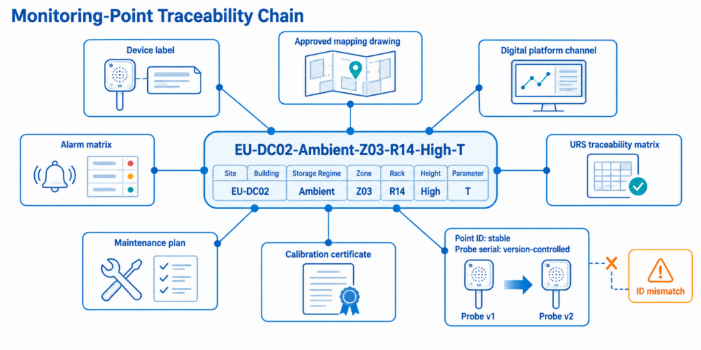
One controlled point identifier should connect the physical label, mapped location, digital channel, calibration evidence, alarm matrix, maintenance plan, and validation traceability.
UbiBot provides public-cloud and on-premises platform options. Current public materials describe device management, real-time and historical data, alerts, exports, data forwarding, API access, and an on-premises platform with local LAN deployment, local data storage, group/authority management, and enterprise API integration. These functions can support a regulated workflow, but the public pages reviewed for this article do not establish that the UbiBot platform, by itself, is a validated 21 CFR Part 11 system. The customer must assess the configured deployment against its intended use and required electronic-record controls. [9,10]
Platform configuration should be approved before routine use. Create device groups that match the quality organization: site, building, storage regime, zone, and responsibility. Configure measurement intervals based on product sensitivity and facility dynamics, then set upload intervals so that alarms arrive within the response time the SOP requires. Local memory should be sufficient for the defined network-outage period.
Alarm settings should come from approved product and zone requirements. A complete workflow normally needs high and low limits, justified delays, recovery logic or hysteresis, device-offline and power-loss alerts, escalation when the first recipient does not respond, and a documented acknowledgement/investigation process. A loading-dock door event should not use the same logic as a sustained ambient-zone excursion if the quality risk is different.
Access control should define who can view records, acknowledge alarms, change thresholds, adjust calibration offsets, add users, export data, change time settings, or remove devices. If electronic signatures, audit trails, or controlled change records are required for the intended use, confirm that the selected platform and operating procedure provide those controls. If not, integrate the measurements into an appropriate validated system rather than treating a general IoT dashboard as a substitute for regulated electronic-record functionality.
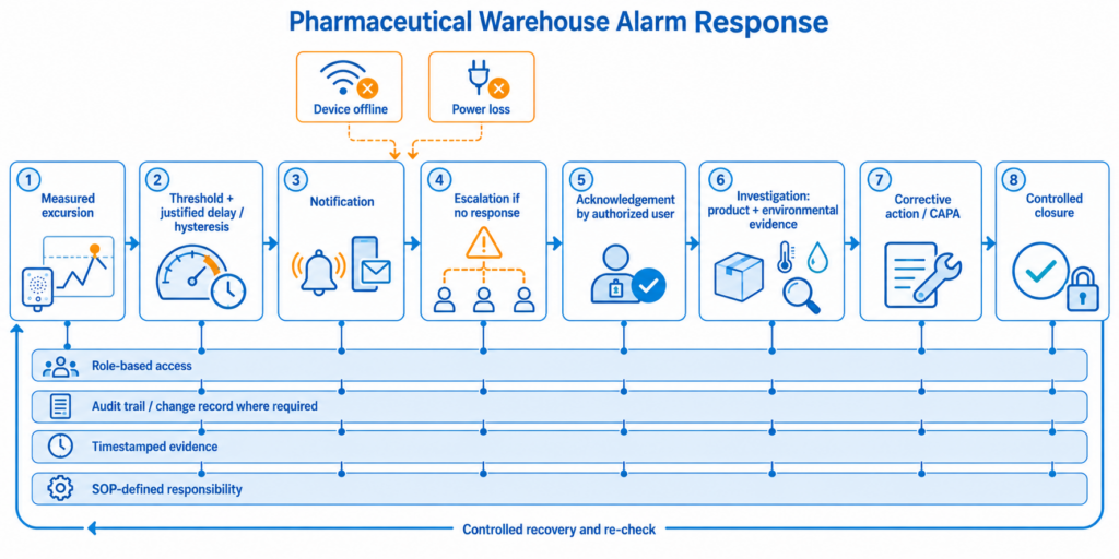
An approved alarm workflow links detection, justified delay and recovery logic, escalation, acknowledgement, investigation, corrective action, and controlled record closure.
5. Validate the Complete Monitoring Chain Before Release
Commissioning should test the system from measurement to response. A plausible value on a dashboard only proves that one data path is working at that moment; it does not demonstrate that the deployed system will remain reliable during alarms, network outages, maintenance, user changes, or data recovery.
The validation lifecycle should be proportionate to the intended use and the company quality system. Many pharmaceutical organizations structure evidence around a URS, risk assessment, design/configuration review, installation qualification, operational testing, and performance verification under routine conditions. The names of the documents may vary, but the evidence should show that requirements are traceable to tested functions and that the released system remains in a controlled state.
At commissioning, compare each permanent sensor or probe against a traceable reference under stable conditions. Record the device ID, probe serial number, reference certificate, test points, observed error, acceptance criterion, date, and responsible person. If the platform permits calibration offsets, treat changes to those offsets as controlled configuration because they can affect displayed values, alarms, and future investigations.
Alarm testing should include the high and low limits actually used in operation, the configured delay, recovery behavior, notification route, escalation, and acknowledgement. Create at least one controlled excursion to verify the full workflow. Repeat the test for device-offline and power-loss conditions if those alarms are part of the URS.
Network-failure testing is equally important. Disconnect communication long enough to confirm that the field device continues recording locally, then restore the connection and verify that missing records are uploaded with the original timestamps and appear in the correct sequence. Check time zones, daylight-saving behavior where applicable, duplicate records, and API retransmission behavior.
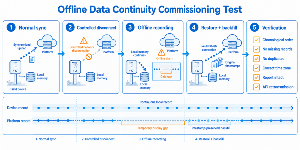
During a communication outage, the field device should continue timestamped recording locally and backfill the missing interval in the correct sequence when the connection is restored.
Electronic-record testing should match the intended regulatory use. Verify user roles, password controls, session behavior, report generation, data export, backup and restore, record retention, security, and audit-trail or signature functions where required. FDA Part 11 and EU Annex 11 are system-level requirements; vendor statements can support qualification, but the regulated company remains responsible for validating the configured application and procedures. [2,4]
Release should be followed by lifecycle controls. Periodically review device health, calibration status, alarm contacts, network performance, user accounts, software/firmware changes, backup success, and data-retention capacity. Reassess sensor locations after major HVAC changes, warehouse expansion, new racking, insulation work, refrigeration replacement, or repeated unexplained excursions. EU GDP specifically expects mapping to be repeated after significant modifications or according to risk assessment. [3]
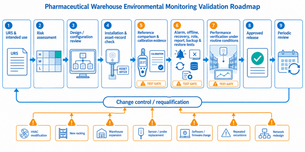
Release depends on traceable evidence from requirements and risk assessment through installation, functional testing, routine performance, periodic review, and controlled change.
6. Scale the Deployment Without Losing GxP Control
Scaling should add standardized structure, not just more sensors. A small controlled room can operate with a few fixed monitors and a limited user group; a multi-site network needs naming standards, configuration templates, role governance, calibration scheduling, API master data, regional permissions, backup design, and formal change control.
| Deployment scale | Typical architecture | Platform approach | Main implementation concern |
| Small controlled room | A few Ethernet/WiFi monitors; external probe only where needed; protected local power. | Public cloud or controlled local platform with a small approved user group. | Mapping evidence, point identity, alarm ownership, and calibration traceability. |
| Single large distribution centre | Multiple zones and heights; Ethernet backbone plus selected RS485/WiFi points; optional redundant network path. | Central groups, role-based access, standardized alarm templates, automated reports, maintenance dashboard. | Consistent installation, network resilience, sensor replacement, and HVAC/racking changes. |
| Multi-site pharmaceutical network | Standard device kit per site; regional network options; controlled API to QMS/WMS/data lake. | Central or on-premises platform with governed master data, permissions, retention rules, and regional reporting. | Global standardization while meeting local regulation, cybersecurity, data residency, and support requirements. |
| High-compliance / validated storage | Mapped extremes, calibrated probes, redundancy where justified, qualified power and network architecture. | Validated electronic-record environment with backup, restoration, auditability, and controlled changes. | Traceability from URS through validation, excursion response, data integrity, and periodic review. |
A useful scaling rule is to standardize everything that should not vary—naming, labels, alarm templates, user roles, calibration records, test protocols, firmware governance, and API field definitions—while allowing site-specific variation only where mapping, network conditions, local regulations, or operating procedures justify it.
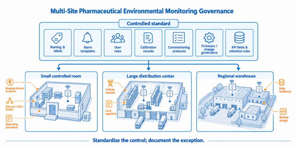
A scalable GxP deployment standardizes naming, alarm templates, roles, calibration records, test protocols, firmware governance, and API data while preserving justified site-specific controls.
7. Verified Product Comparison for GxP Pharmaceutical Warehouse Deployment
The systems below represent different deployment models rather than identical products. Specifications are based on current official manufacturer pages or data sheets reviewed for this article. Where the public source does not state a value, the table says “Not publicly specified” rather than estimating it. Compliance statements are vendor claims or regulatory-positioning statements and do not replace customer validation.
| Comparison item | UbiBot GS1-AETH1RS | Testo Saveris 1 | Vaisala viewLinc + RFL100 | ELPRO ECOLOG-PRO xG | DicksonOne + DWE2 |
| Configured hardware | GS1-AETH1RS built-in T/RH; optional TH30S-B or PT100 RS485 probe; UbiBot Platform | testo 150 TUC4 + digital T/RH probe 0572 2165 + Saveris Base / communication module | RFL100 logger + HMP110 T/RH probe + AP10 access point + viewLinc | ECOLOG-PRO 1THGi + elproCLOUD (current xG architecture) | DWE2 + RTRH-R replaceable T/RH sensor + DicksonOne |
| Temperature range | Built-in: -20 to 60°C. TH30S-B: -40 to 80°C. | 0572 2165: -30 to 50°C. | HMP110: -40 to 80°C. | 1THGi internal sensor: -40 to 70°C. | RTRH-R: -40 to 85°C. |
| Temperature accuracy | Built-in: ±0.2°C. TH30S-B accuracy not publicly specified on current product page. | 0572 2165 system accuracy: ±0.4°C at 25°C. | HMP110 digital output: ±0.1°C at 15-25°C; ±0.15°C at 0-15°C and 25-40°C. | 1THGi: ±0.4°C across -40 to 70°C in current technical spec. | RTRH-R: ±0.4°C from 20 to 120°F; ±1.0°C remaining range per current sensor table. |
| Humidity range | Built-in: 10-90% RH non-condensing. TH30S-B: 0-100% RH. | 0572 2165: 0-100% RH, non-condensing. | HMP110: 0-100% RH. | 1THGi: 0-100% RH non-condensing. | RTRH-R: 5-95% RH non-condensing. |
| Humidity accuracy | Built-in: ±2% RH. TH30S-B accuracy not publicly specified on current product page. | ±2.0% RH at 0-90% RH at 25°C. | ±1.5% RH at 0-90% RH, 0-40°C; ±2.5% RH at 90-100% RH. | ±2.5% RH at 0-90% RH; ±3.5% RH at 90.1-100% RH (23°C). | ±2.0% RH from 5-95% RH. |
| Connectivity | RJ45 Ethernet + 2.4 GHz WiFi; selected RS485 external probes. | WLAN, Ethernet, or testo UltraRange via communication modules. | VaiNet proprietary LoRa-based radio from RFL100 to AP10; AP10 uses wired Ethernet. | LTE-M / NB-IoT global roaming; direct cellular cloud architecture. | WiFi or Ethernet to DicksonOne. |
| Offline / local continuity | 300,000 sensor records on GS1-AETH1RS. | Saveris Base V3.0 uses circular buffer; official brochure lists up to 120,000,000 values and 40,000 per channel at the base. | RFL100: 30-day buffer, 43,200 samples per channel at 1-minute sampling. | 31,000 measurement values. | Approx. 400,000 sample points backup. |
| Power / backup | Internal lithium battery plus Type-C / DC input; optional PoE shown on current product page. Official UbiBot pages reviewed show inconsistent battery-capacity values, so confirm hardware revision. | testo 150 modules use batteries; mains accessories available. Saveris Base supports PoE/mains and has Li-ion backup for data backup/emergency alarm. | RFL100 battery-powered; AP10 powered by PoE or DC adaptor. | 2 x AA alkaline or LiFe batteries; up to 14 months stated, depending on conditions. | 120-240 VAC / 12 VDC; average 72-hour battery backup. |
| Platform / records | UbiBot public or on-premises platform; alerts, history, exports, API/data forwarding, group/authority management depending deployment. | Saveris CFR On-Prem: user management, audit trail/ERES concept, alarm escalation, reports, mobile acknowledgement. | viewLinc: real-time trends, alarms, reports, remote access, multi-site scaling, GxP-oriented monitoring. | elproCLOUD: real-time cellular monitoring, event-driven alerts, validated GAMP 5 / Part 11 vendor positioning. | DicksonOne: cloud monitoring, email/SMS alerts, secure data, scalable multi-location access. |
| Calibration / validation | Confirm certificate and traceability package for the exact GS1/probe SKU. Public pages reviewed do not establish standalone Part 11 validation. | Digital probes can be replaced/calibrated without logger downtime; calibration protocol included; CFR software positioned for 21 CFR Part 11/EU Annex 11 workflows. | HMP110 supplied with calibration certificate; viewLinc positioned for GxP-regulated environments. | Manufacturer validation certificate plus 3-point calibration certificate; ISO 17025 traceability options stated. | NIST-traceable calibration options available for RTRH-R; validate DicksonOne configuration for intended regulated use. |
| Best deployment fit | Infrastructure-light fixed Ethernet/WiFi monitoring where local storage, mixed connectivity, API access, and optional on-premises deployment are priorities. | Pharma sites wanting a mature modular EMS with dedicated CFR software, replaceable digital probes, and structured validation workflows. | Enterprise and multi-site GxP facilities prioritizing high-accuracy probes, long-range wireless networking, and mature viewLinc controls. | Warehouses or rooms needing independent cellular loggers with minimal local IT infrastructure and a GxP-focused cloud workflow. | Facilities wanting straightforward WiFi/Ethernet cloud logging with replaceable calibrated sensors and strong backup capacity. |
Source note: Reconfirm model revisions, software versions, subscriptions, calibration packages, and regional availability before publication or procurement. “GxP/Part 11” references in this table describe vendor positioning or functions; customer validation remains required for the intended use.
The UbiBot architecture is the simplest of the five when a warehouse already has approved Ethernet or WiFi and wants each point to combine sensing, display, local storage, and direct platform connectivity. It can reduce the number of infrastructure layers compared with gateway-centric systems. Its main GxP project question is not basic monitoring capability but validation evidence: the customer must confirm calibration traceability, platform controls, auditability, change management, and electronic-record requirements for the intended regulated use.
Testo Saveris 1, Vaisala viewLinc, and ELPRO are stronger regulated-life-science benchmarks because their product portfolios and software are explicitly built around GxP workflows. Testo emphasizes modular probes and CFR software; Vaisala combines high-accuracy probes with the VaiNet/viewLinc architecture; ELPRO xG offers IT-independent cellular deployment with GAMP 5 and Part 11 vendor positioning. DicksonOne provides a comparatively straightforward cloud architecture with replaceable calibrated sensors and substantial local backup. These differences make the systems useful comparison points even though they are not identical device classes.
8. Frequently Asked Questions
What is a GxP environmental monitoring system in a pharmaceutical warehouse?
It is a controlled monitoring process that combines qualified sensors, mapped monitoring points, reliable communications, alarm handling, calibrated measurements, electronic records, user access, maintenance, and validation evidence. GxP suitability depends on the intended use and applicable GMP/GDP requirements, not on the sensor alone.
How many temperature and humidity sensors does a pharmaceutical warehouse need?
There is no reliable universal number based only on floor area. The count and location should come from temperature mapping, storage height, HVAC design, door activity, independently controlled zones, product risk, and repeated hot/cold patterns. Permanent monitoring points should cover mapped extremes and critical operational zones.
Where should permanent sensors be placed after warehouse temperature mapping?
Place them at representative locations that repeatedly show high and low conditions and at zones that require independent control. Avoid direct supply air, sunlight, wall surfaces, floors, roof structures, or locations that stock can block unless the point is intentionally monitoring that specific risk.
Does a pharmaceutical warehouse always need humidity monitoring?
Not always as a formal release criterion. Monitor RH when the product specification, packaging system, regulatory filing, condensation risk, HVAC strategy, or quality risk assessment makes it relevant. If there is no approved humidity limit, do not create one simply because the device can measure humidity.
Is Ethernet better than WiFi for GxP warehouse monitoring?
Ethernet is usually more predictable for permanent fixed points and is easier to place on a controlled network. WiFi is useful for retrofits and hard-to-cable areas, but coverage must be tested under loaded warehouse conditions. The correct design may also include RS485, long-range wireless, or cellular links depending on site constraints.
Does using a cloud monitoring platform make the system 21 CFR Part 11 compliant?
No. Part 11 applies to electronic records within its scope, and compliance depends on the configured system and operating controls. Validation, access control, audit trails where applicable, record retention, security, signatures where required, procedures, training, backup, and change control must be assessed for the intended use.
How should alarm delays be set in a pharmaceutical warehouse?
Use product stability, mapped recovery behavior, HVAC response, door-opening patterns, and the time available for corrective action. The threshold, delay, hysteresis or recovery logic, escalation path, and written response procedure should be approved together. A delay should reduce nuisance alarms without hiding a meaningful excursion.
What should happen if the network or cloud connection fails?
The field device or local architecture should continue recording for the required outage period. When communication returns, stored records should be uploaded with their original timestamps. This behavior, along with offline alarms, backup power, report integrity, and API recovery, should be tested during commissioning.
A dependable GxP pharmaceutical warehouse monitoring deployment begins with product requirements and mapping evidence, then connects permanent sensor placement, network reliability, controlled alarm workflows, electronic-record governance, validation, and lifecycle maintenance. The correct architecture may be a small group of Ethernet monitors, a proprietary long-range wireless network, direct cellular IoT loggers, or a validated enterprise EMS. The choice should reflect warehouse risk and regulated use rather than one headline specification.
For sites that prioritize mixed Ethernet/WiFi connectivity, local data storage, API access, and optional on-premises deployment, the UbiBot GS1-AETH1RS can provide a practical monitoring foundation. Before the system is used for GxP-critical records, however, the project should confirm the exact probe and calibration package, current hardware revision, platform feature set, validation evidence, and the organization’s Part 11/Annex 11 requirements.
Product and Regulatory Sources
[1] 21 CFR 211.142 – Warehousing procedures (US CFR, current official text via GovInfo) – https://www.govinfo.gov/content/pkg/CFR-2025-title21-vol4/pdf/CFR-2025-title21-vol4-part211.pdf
[2] FDA Guidance for Industry – Part 11, Electronic Records; Electronic Signatures – Scope and Application – https://www.fda.gov/regulatory-information/search-fda-guidance-documents/part-11-electronic-records-electronic-signatures-scope-and-application
[3] European Commission – Guidelines on Good Distribution Practice of medicinal products for human use (2013/C 343/01) – https://health.ec.europa.eu/document/download/9f28179a-a6f8-418a-a5fc-ecfbb3ae3ba8_en
[4] EudraLex Volume 4, Annex 11 – Computerised Systems – https://health.ec.europa.eu/system/files/2016-11/annex11_01-2011_en_0.pdf
[5] WHO – Temperature mapping of storage areas / cold chain and dry store temperature mapping guidance – https://www.who.int/publications/m/item/Annex-9-g-trs-961
[6] UbiBot GS1-AETH1RS official specifications / product page – https://store.ubibot.com/en-sg/pages/ubibotgs1-aeth1rs_specifications
[7] UbiBot TH30S-B official product page – https://store.ubibot.com/products/temperature-and-humidity-probe
[8] UbiBot PT100 industrial-grade temperature probe official specifications – https://store.ubibot.com/ja/pages/pt100industrial-gradetemperatureprobe_specifications
[9] UbiBot On-Premises Platform official page – https://www.ubibot.com/on-premises-platform/
[10] UbiBot Platform/API documentation hub – https://www.ubibot.com/category/app-platform-api/