

UBiBot Logo
UBiBot Logo
  • UBiBot Logo
  • Home
  • Products

    NEW

  • Pricing
  • Support
  • About Us
  • Download
  • magnifying-glass  Search
  • magnifying-glass header-close
  • Sign in Sign in
    Public Web Console Public Web Console
    On-Premises App Center On-Premises App Center
  • Home
  • Products

    NEW

  • Pricing
  • Support
  • About us
  • Download
  •  Public Web Console
  •  On-Premises App Center
  • Where to Buy

Learn Hub

Explore Knowledge Academic Research In-depth Tech

Share

LinkedIn

Facebook

X (Twitter)

Newsletter Signup

Table of contents

    Greenhouse Sensor System Deployment Guide

    Introduction

    Once a commercial greenhouse has decided to install environmental monitoring, the main challenge is no longer whether sensors are useful. The challenge is deciding what each sensor should represent, how many monitoring zones are needed, where a LoRa gateway can communicate reliably, and how alerts should be handled without creating constant false alarms.

    A sensor placed beside a heater, evaporative cooling pad, roof vent, misting nozzle or sunlit structural member can report a real local condition while still giving a misleading picture of the crop environment. The same problem appears when one device is expected to represent several bays, different crop heights or greenhouse sections with separate ventilation and irrigation patterns. USDA research has shown that greenhouse temperature and humidity can vary across physical locations, so a deployment should be designed around measurable microclimates rather than floor area alone. [1]

    The communication architecture also needs to match the site. WiFi can work in a compact greenhouse with reliable coverage, but large structures, multiple houses and outdoor production blocks often benefit from low-power long-range communication. A LoRa system reduces field wiring, but it still requires careful gateway placement, region-appropriate radio frequencies, stable backhaul and a maintenance plan for batteries and sensors.

    Deployment principle

    Place each monitoring point where it represents the crop and the climate-control zone. Do not place sensors where installation is convenient but the local reading is dominated by direct sun, irrigation water, heaters, fans or vents.
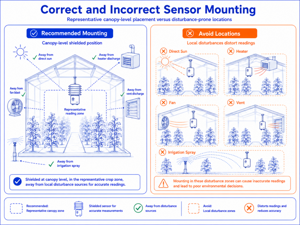
    Correct and incorrect sensor mounting

    1.Survey the Greenhouse Before Selecting Hardware

    A greenhouse survey should convert the physical site into monitoring zones before any device is purchased. The survey needs to record how the structure is divided, how air and water move, where power and network services are available, and which crop areas have different operating targets.
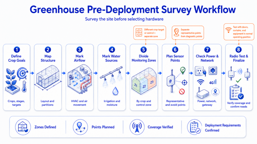
    Greenhouse pre-deployment survey work flow

    Start with the greenhouse layout. Record the number and length of bays, ridge height, sidewall height, internal partitions, insect screens, thermal curtains and connecting corridors. Mark the heating pipes, unit heaters, cooling pads, circulation fans, exhaust fans, roof vents and side vents. Irrigation lines, fogging systems and misting nozzles also matter because water can create short-lived humidity peaks and can damage devices that are not protected from direct spray.

    The crop plan is equally important. Seedling benches, propagation zones, mature crops and vertical growing layers may require different monitoring heights and thresholds. A single greenhouse can also contain several cultivars with different temperature or vapor-pressure-deficit targets. Where separate heating, ventilation or irrigation controls serve different sections, each control zone should normally be treated as a separate monitoring zone.

    Network and power conditions should be documented during the same visit. Identify possible gateway positions, available AC or PoE power, Ethernet ports, WiFi coverage and cellular signal strength. A 4G gateway can simplify remote sites, but the SIM, data plan and regional network compatibility should be confirmed before installation. For wired options, note safe cable routes and the distance between sensors, control panels and the network cabinet.

    The radio survey should be performed with doors, curtains and equipment in their normal operating positions. Wet foliage, metal frames, water tanks and insulated walls can reduce radio performance. A line-of-sight range stated by a manufacturer is not a guaranteed range inside a greenhouse. Test candidate node positions from the intended gateway location and keep a record of signal quality before final mounting.

    3.Plan Sensor Positions Around the Crop Canopy

    The primary air-temperature and humidity sensor should normally be installed at crop-canopy height in a representative part of the growing zone. Cooperative Extension guidance recommends placing greenhouse sensors where they are not directly influenced by heaters, vents, fans or drafts and shielding them from direct sunlight. [2]

    Canopy height changes during the production cycle, so the mounting method should allow the sensor to move. A fixed sensor that begins at canopy height may end up below dense foliage later in the season, where humidity is higher and airflow is lower. Adjustable poles, suspended brackets or rail-mounted supports make it easier to maintain a representative height without rebuilding the installation.

    Direct solar radiation is a common source of error. An air sensor should be placed in a ventilated radiation shield or in another arrangement that allows airflow while preventing the sensor body from heating in the sun. The enclosure should not be sealed in a way that traps warm, humid air. When crop protection chemicals or high-pressure washing are used, the sensing element should be protected according to the manufacturer’s environmental limits and removed or covered if the procedure could damage it.

    The central crop zone is usually the best location for a representative control point, but one central sensor is not enough when the greenhouse has clear microclimates. Add monitoring points near the warm and cool ends, across long bays, beside different heating circuits, and in sections separated by curtains or doors. A sensor close to an entrance, vent or cooling pad is useful as a diagnostic point, but it should not be the only point used to judge the entire greenhouse.

    Vertical differences also matter. Tall crops and multi-layer farms can have different temperature, humidity and light conditions at lower, middle and upper levels. In these cases, deploy sensors at the crop layers that influence growth rather than placing every device at one standard wall height. A reference sensor outside the greenhouse can help the operator compare internal control performance with external weather.
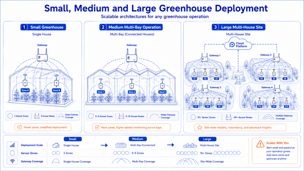
    Small, medium and large greenhouse deployment

    Greenhouse scale Typical zoning approach Sensor placement approach Gateway approach
    Small single house One main crop zone plus entrance or equipment risk points One representative canopy point, with extra points only where heat, cooling or door effects require them Indoor gateway near the house, with verified backhaul
    Medium multi-bay site Separate bays or climate-control sections Canopy points across sections and at known warm/cool ends; add vertical points for tall crops Central gateway or outdoor gateway positioned above local obstructions
    Large multi-house operation Each house and control zone managed as a distinct group Repeated placement template plus diagnostic points near equipment and transition zones One or more gateways with overlap, documented node assignment and central platform management

    4.Choose the Sensors, Power and Communication Architecture

    A greenhouse system should be selected as an architecture rather than as a single sensor. The decision covers measurement range and accuracy, local storage, enclosure protection, battery or external power, radio frequency, gateway backhaul, platform functions and future expansion.

    Temperature and relative humidity are the base measurements for most greenhouse deployments. Many commercial sites also need soil or substrate moisture, CO2, light or photosynthetically active radiation, atmospheric pressure, water leakage and equipment-status inputs. The first installation does not need to include every parameter, but the gateway and platform should have a clear expansion path if the greenhouse plans to automate irrigation, ventilation or climate control later.

    For a distributed LoRa deployment, the UbiBot DC1-L-THP can measure temperature, relative humidity and atmospheric pressure. Its published temperature range is -20°C to 60°C, with ±0.2°C accuracy from 0°C to 60°C. Relative humidity is measured from 0% to 100% RH, with ±2% RH accuracy from 10% to 90% RH. The device is rated IP65, stores up to 50,000 records and supports battery or 12 VDC power. [3]
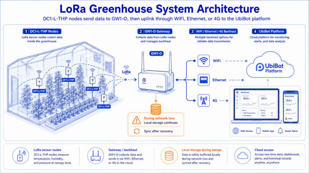
    LoRa greenhouse system architecture

    The node communicates with a UbiBot GW1 gateway. The indoor GW1 supports WiFi, Ethernet and, on the 4G version, cellular backhaul. The outdoor GW1-O is IP65 and offers Ethernet with either WiFi or mobile-network connectivity, depending on the selected model. UbiBot states that one GW1 can manage up to 100 LoRa sensors and that communication can reach up to 1 km in ideal outdoor conditions. These figures are useful for planning but still require an on-site radio test. [4]

    The gateway frequency must match local radio regulations and the sensor nodes. UbiBot lists RU864, IN865, EU868, US915, AU915, KR920 and AS923 variants. A global buyer should not order one frequency version for every country without checking the destination market. The sensor, gateway and antenna must be configured for the same regional band.

    LoRa is most useful when a greenhouse has many low-data-rate nodes spread across a large site. WiFi remains practical for a compact greenhouse with reliable access-point coverage. Direct 4G devices are useful when only a few independent points are needed and no local gateway is preferred. Ethernet and RS485 provide stable fixed connections but increase cabling work and can be difficult to retrofit around active crop rows. The best architecture may combine LoRa field nodes with Ethernet or 4G backhaul from the gateway.

    5.Install the LoRa Nodes and Gateway

    Install the sensor nodes only after the monitoring plan and radio survey have been approved. Each node should be mounted securely, protected from direct water spray and placed where the sensing element can exchange air freely. The device label, platform name and maintenance record should use the same identifier.

    A practical naming convention can combine site, greenhouse, zone, crop and height. For example, GH02-TOMATO-EAST-CANOPY identifies the second greenhouse, tomato crop, eastern section and canopy-level sensor. Clear names reduce errors when the platform contains dozens of similar devices and make alarm messages easier to understand.
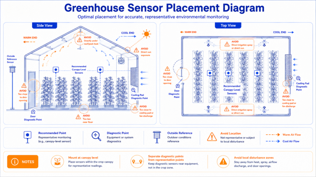
    Greenhouse sensor placement diagram

    Keep antennas clear of large metal objects and water-filled structures where possible. Antennas should normally remain in the orientation recommended by the manufacturer, and node enclosures should not be hidden behind metal control cabinets. The gateway is usually mounted higher than the crop canopy and near the centre of the radio coverage area. An outdoor-rated gateway is preferable when the only suitable position is exposed to condensation, rain or wash-down.

    Gateway backhaul should be tested separately from the LoRa link. A node may communicate successfully with the gateway while the gateway itself cannot reach the cloud. Confirm Ethernet, WiFi or cellular operation, then interrupt the backhaul and verify that local data is retained and uploaded after the connection returns. The UbiBot GW1 stores up to 300,000 sensing records, which provides a buffer during temporary network interruptions. [4]

    Power design affects maintenance. Battery-powered nodes reduce installation work but need a documented replacement schedule. High sampling and transmission frequency, weak radio links and low temperatures can reduce battery life. Gateways should normally use a permanent, protected power source. Where PoE is available, it can simplify installation by carrying power and Ethernet through one cable. Surge protection and appropriate electrical work are important for outdoor agricultural sites.

    6.Configure the Cloud Platform, Alerts and Data Workflow

    The platform should be configured around greenhouse operations rather than device serial numbers. Bind the gateway and nodes, assign them to site and greenhouse groups, then verify that every channel displays the correct parameter and location.

    Choose the sensing interval according to how quickly the greenhouse changes and what decisions the data supports. A short interval gives more detail during ventilation, heating or irrigation events, but it increases data volume and power use. The upload interval can be different from the sensing interval when the device stores readings locally. During commissioning, shorter intervals help reveal microclimates; after the system is understood, the settings can be adjusted to the operational need.

    Alarm thresholds should follow the crop stage and the greenhouse operating plan. Propagation areas, flowering crops and mature fruiting crops may require different limits. A single threshold for every greenhouse can create unnecessary alarms or hide a problem. Use separate high and low limits for temperature and humidity, add a delay or hysteresis where the platform supports it, and configure offline-device and low-battery warnings as well as environmental alarms.

    The notification workflow should define who acts on each type of alarm. A night-time heating alarm may go to the duty manager and maintenance technician, while a high-humidity warning may first go to the grower. Escalation should be tested so that a missed message does not leave the greenhouse without a response.

    UbiBot offers a public cloud platform for rapid deployment, an on-premises platform for local data control, and APIs or data-forwarding services for integration. The selected package determines which functions and limits apply, so user accounts, reporting, data retention, automated exports and API requirements should be confirmed before a large rollout. [5]

    For multi-site operations, create consistent group names, alarm templates and user roles. Growers may need trend access, technicians may need device and battery status, and corporate managers may need summary dashboards across several sites. Restrict configuration changes to authorised users so that thresholds and sampling intervals are not altered without approval.

    7.Commission, Validate and Maintain the System

    Commissioning proves that the installed system measures the intended zone, communicates reliably and sends alerts to the correct people. It should be completed before the data is used for crop decisions or automated control.

    Begin with a side-by-side check using a trusted reference instrument. Place the reference and installed sensor together in a stable, shaded location and allow enough time for both to reach equilibrium. Record the serial numbers, date, location and observed differences. This field check does not replace accredited calibration when a customer requires it, but it can identify damaged sensors, configuration mistakes and major offsets.

    Next, test the radio link with the greenhouse in normal operating condition. Close doors and curtains, operate fans and irrigation, and confirm that each node reports consistently. Temporarily disconnect the gateway backhaul to test local storage and automatic recovery. Create a controlled alarm by changing a threshold or moving a test sensor, then confirm the alert, escalation and acknowledgement workflow.

    Validation should also compare the monitoring points. Review several days of data to identify locations that move together and locations that behave differently. If one point consistently shows a separate pattern, investigate whether it represents a genuine microclimate or an installation problem such as direct sun, a nearby nozzle or restricted airflow.

    The maintenance plan should include sensor cleaning, enclosure inspection, battery replacement, radio and backhaul checks, calibration review and platform user review. Reassess sensor height as crops grow, and repeat the placement review after structural changes, new curtains, different crops or modifications to heating and ventilation. Seasonal conditions can also justify a second radio and microclimate survey.

    Acceptance record

    Keep one commissioning record that links the reference comparison, final sensor and gateway positions, LoRa and Internet-recovery tests, alarm recipients, device names, maintenance owner and seasonal review date.
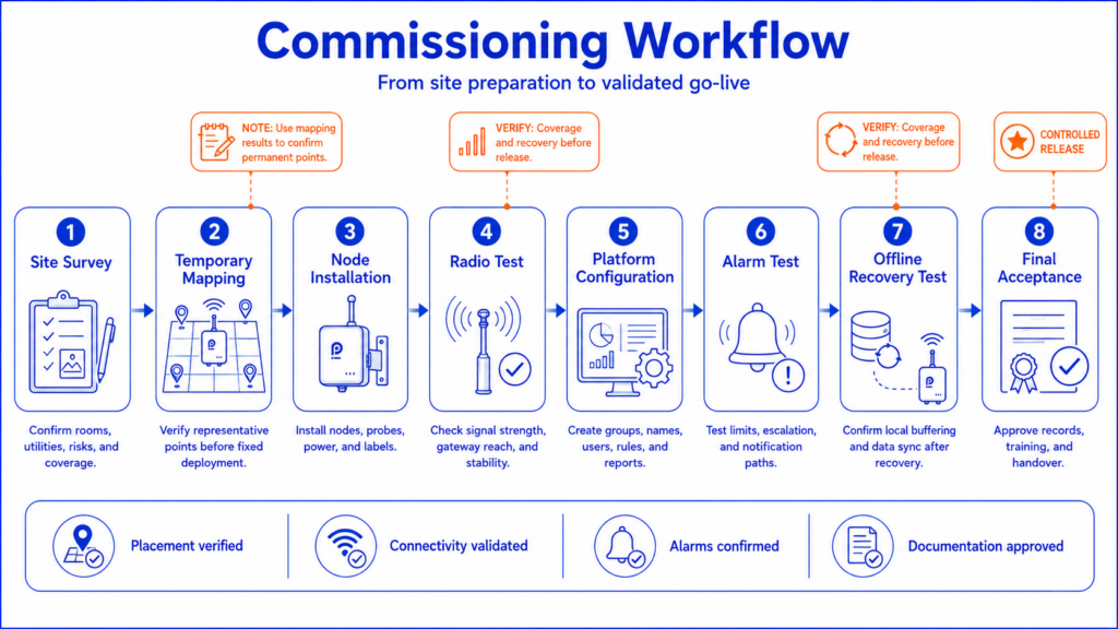
    Commissioning workflow

    8.Comparison of Greenhouse Monitoring Systems

    The products below represent four different wireless deployment routes. The comparison focuses on the exact sensor-and-gateway combinations needed to operate a greenhouse monitoring system; it does not assume that every wireless product uses LoRa.

    Comparison item UbiBot DC1-L-THP GW1-24F4G Monnit MNS2-9-IN-HU-RH-L03 ALTA Industrial IoT Gateway Sensaphone WSG30 FGD-WSG30-HUM / FGD-WSG30-TMP AKCP SP-WT + THS01 Wireless Tunnel Server
    Wireless architecture LoRa nodes to UbiBot GW1 gateway; WiFi/Ethernet/4G backhaul Monnit proprietary ALTA FHSS sensor network to cellular/Ethernet gateway 2.4 GHz WSG wireless sensors to Ethernet WSG30 base LoRa-based proprietary Wireless Tunnel to local gateway-server
    Temperature range -20 to 60°C -25 to 70°C with leded humidity probe FGD-WSG30-TMP: 0 to 57°C; external-probe models offer wider ranges THS01: -55 to 75°C
    Temperature accuracy ±0.2°C from 0 to 60°C ±0.3°C typical; ±0.5°C maximum ±0.56°C ±0.5°C from -10 to 75°C on sensorProbe+ / securityProbe systems
    Humidity range and accuracy 0 to 100% RH; ±2% RH from 10 to 90% RH 0 to 100% RH ±3% RH typical, ±5% RH maximum FGD-WSG30-HUM: 0 to 95% RH; ±3% from 20 to 80%, ±5% otherwise 0 to 100% RH; published accuracy ±2% RH minimum to ±5% RH maximum at 25°C
    Local data buffer 50,000 records in node and 300,000 records in gateway Sensor logs 2,000 to 4,000 readings if gateway connection is lost WSG30 stores up to 67,000 samples Local gateway-server architecture; exact sensor-side buffer not publicly specified
    Power Node: AA / Li-SOC12 / DC 12V; outdoor gateway: DC 12V / PoE Industrial lithium battery for sensor powered cellular gateway Sensors: 2 AA batteries or optional power; WSG30 has plug-in power and 2-hour backup SP-WT: external 5V or battery options; THS01 powered by SP-WT; server requires external power
    Environmental protection DC1-L-THP and GW1 are IP65 Industrial sensor enclosure is IP65; industrial gateway is NEMA 4 / IP65 Standard plastic indoor sensor housings; no IP rating published for the listed WSG sensors SP-WT operating environment -15 to 50°C and 20 to 80% RH non-condensing; enclosure rating not publicly specified
    Network scale Gateway supports up to 100 UbiBot LoRa sensors Gateway capacity depends on selected ALTA gateway; Ethernet gateways support up to 100 sensors, higher-capacity models available Up to 30 WSG wireless sensors per WSG30 Wireless Tunnel Server: up to 30 wireless devices and up to 400 total sensors
    Platform approach UbiBot public cloud, on-premises platform, API and data forwarding options iMonnit cloud or compatible local options Web access, email/email-to-text, SNMP and Modbus from the WSG30 Local Wireless Tunnel Server and AKCP software; optional 4G on server
    Best-fit deployment Large greenhouse or multi-house site needing LoRa nodes, flexible backhaul and central cloud management Industrial wireless deployment needing rugged sensors and Monnit ecosystem Smaller fixed sites where 30 indoor wireless sensors and local Ethernet are sufficient Private local LoRa-style network where local server control and AKCP sensor expansion are priorities

    The UbiBot configuration is closest to a greenhouse-wide LoRa deployment. It combines IP65 field hardware, multiple backhaul choices and cloud or on-premises data management. Its main implementation requirement is correct regional frequency selection and a verified gateway location.

    Monnit offers a rugged industrial sensor and a mature gateway ecosystem, but the ALTA radio is proprietary FHSS rather than LoRa. This distinction matters when a buyer is comparing radio standards or expects interoperability with third-party LoRaWAN gateways. The system is best evaluated as an integrated Monnit architecture. [6]

    Sensaphone WSG30 is a practical wireless monitoring system, but its listed humidity and room-temperature sensors are intended for clean indoor environments and have a shorter published wireless range. It is more suitable for a compact greenhouse service area or a protected installation than for exposed, high-condensation crop zones unless additional protection is provided.

    AKCP uses LoRa radio technology within its proprietary Wireless Tunnel platform. It is attractive when the operator wants local reporting, a private gateway-server and a broad range of AKCP intelligent sensors. The architecture is more infrastructure-oriented than a simple cloud-first sensor network.

    Site condition Practical starting architecture
    Several greenhouses with central cloud management UbiBot LoRa nodes with one or more GW1 gateways and consistent site/zone naming
    Rugged proprietary wireless ecosystem is preferred Monnit ALTA sensors with an ALTA gateway and iMonnit management
    Compact protected site with reliable Ethernet Sensaphone WSG30 with the exact wireless temperature and humidity sensors required

    9.Frequently Asked Questions

    How many sensors does a commercial greenhouse need?

    There is no universal number. Start with one representative canopy-level point in each climate-control zone, then add points where long bays, separate heating circuits, curtains, entrances, crop layers or known warm and cool areas create different conditions. A short mapping study is more reliable than using floor area alone.

    Where should temperature and humidity sensors be placed in a greenhouse?

    Place the main sensor at crop-canopy height in a representative growing area. Shield it from direct sun and keep it away from heaters, fans, vents, drafts, cooling pads and irrigation spray. Door and equipment locations can be monitored as diagnostic points, but they should not be the only points used to represent the crop zone.

    Is LoRa better than WiFi for greenhouse monitoring?

    LoRa is usually better for many low-power sensors spread across large greenhouses or several structures. WiFi is simpler when coverage is already reliable and only a few devices are needed. LoRa still needs a gateway and does not remove the need for Ethernet, WiFi or cellular backhaul to the platform.

    Where should the LoRa gateway be installed?

    Mount the gateway above most crop and structural obstructions, near the centre of the required coverage area and close to a stable power and backhaul connection. Use an outdoor-rated gateway when the position is exposed. Test every node location with the greenhouse in normal operating condition before final mounting.

    How often should greenhouse sensors record data?

    The interval should match the speed of the climate changes and the purpose of the data. Short intervals are useful during commissioning and for fast ventilation or heating events. Longer intervals reduce data volume and battery use. The final setting should be based on the crop, control system and response process.

    Should greenhouse alarm limits be the same for every crop?

    No. Alarm limits should reflect crop type, growth stage, time of day and the operating targets for each zone. Propagation, flowering and mature crops may need different limits. Use delays or hysteresis carefully so short control cycles do not create false alarms.

    What happens if the gateway loses Internet access?

    A suitable system should continue recording locally and upload the missing data after the connection returns. This behaviour must be tested during commissioning. The UbiBot DC1-L-THP stores 50,000 records and the GW1 gateway stores up to 300,000 sensing records.

    How often should greenhouse sensors be calibrated?

    Set a documented interval based on the required accuracy, sensor stability, operating conditions and customer quality requirements. Perform additional checks after chemical exposure, water ingress, physical damage or unexplained drift. A field comparison can identify problems but does not replace accredited calibration when formal traceability is required.

    10.A Practical Deployment Decision

    A successful greenhouse monitoring system begins with zoning and sensor placement, not with a device count. The primary sensors should follow the crop canopy and represent each climate-control zone, while additional points should explain known risks such as doors, cooling pads, heaters and vertical crop layers.

    LoRa is a strong choice for large or multi-house sites because it reduces field wiring and allows many low-power nodes to share one gateway. The gateway still needs stable power, a verified radio position and dependable WiFi, Ethernet or cellular backhaul. A pilot deployment should test all three layers: the sensor reading, the LoRa link and the gateway connection to the platform.

    For sites that need IP65 field nodes, flexible gateway backhaul and cloud or on-premises management, the UbiBot DC1-L-THP and GW1-O form a practical starting architecture. The final design should still be adjusted to local radio bands, greenhouse structure, crop requirements and the maintenance capacity of the operating team.

    11.Product and Technical Source List

    [1] USDA Agricultural Research Service: Testing a multi-brand sensor node to monitor greenhouse variability. Evidence that greenhouse environmental conditions can vary across locations.

    [2] University of Alaska Fairbanks Cooperative Extension: Controlling the Greenhouse Environment. Guidance on canopy-level placement and avoiding heaters, vents, fans, drafts and direct sun.

    [3] UbiBot DC1-L-THP official specifications. Temperature, humidity, pressure, power, storage and IP65 specifications.

    [4] UbiBot GW1 and GW1-O official specifications. Gateway backhaul, storage, power and regional LoRa bands. See also the GW1-O specifications for the outdoor model.

    [5] UbiBot platform deployment options and APIs. Public cloud, on-premises and developer integration options.


    Related Resources

    No related resources found

    menu-header-svg
    Search
    • Explore Knowledge
      • Comparison & Selection
      • Industry Solution
      • Product & Device
      • Criterion & Compliance
      • Deployment & Usage
      • Technology & Principle
    • Academic Research
    • In-depth Tech

    learn

    See More >>

    Greenhouse Sensor System Deployment Guide

    Introduction

    Once a commercial greenhouse has decided to install environmental monitoring, the main challenge is no longer whether sensors are useful. The challenge is deciding what each sensor should represent, how many monitoring zones are needed, where a LoRa gateway can communicate reliably, and how alerts should be handled without creating constant false alarms.

    A sensor placed beside a heater, evaporative cooling pad, roof vent, misting nozzle or sunlit structural member can report a real local condition while still giving a misleading picture of the crop environment. The same problem appears when one device is expected to represent several bays, different crop heights or greenhouse sections with separate ventilation and irrigation patterns. USDA research has shown that greenhouse temperature and humidity can vary across physical locations, so a deployment should be designed around measurable microclimates rather than floor area alone. [1]

    The communication architecture also needs to match the site. WiFi can work in a compact greenhouse with reliable coverage, but large structures, multiple houses and outdoor production blocks often benefit from low-power long-range communication. A LoRa system reduces field wiring, but it still requires careful gateway placement, region-appropriate radio frequencies, stable backhaul and a maintenance plan for batteries and sensors.

    Deployment principle

    Place each monitoring point where it represents the crop and the climate-control zone. Do not place sensors where installation is convenient but the local reading is dominated by direct sun, irrigation water, heaters, fans or vents.

    Correct and incorrect sensor mounting

    1.Survey the Greenhouse Before Selecting Hardware

    A greenhouse survey should convert the physical site into monitoring zones before any device is purchased. The survey needs to record how the structure is divided, how air and water move, where power and network services are available, and which crop areas have different operating targets.

    Greenhouse pre-deployment survey work flow

    Start with the greenhouse layout. Record the number and length of bays, ridge height, sidewall height, internal partitions, insect screens, thermal curtains and connecting corridors. Mark the heating pipes, unit heaters, cooling pads, circulation fans, exhaust fans, roof vents and side vents. Irrigation lines, fogging systems and misting nozzles also matter because water can create short-lived humidity peaks and can damage devices that are not protected from direct spray.

    The crop plan is equally important. Seedling benches, propagation zones, mature crops and vertical growing layers may require different monitoring heights and thresholds. A single greenhouse can also contain several cultivars with different temperature or vapor-pressure-deficit targets. Where separate heating, ventilation or irrigation controls serve different sections, each control zone should normally be treated as a separate monitoring zone.

    Network and power conditions should be documented during the same visit. Identify possible gateway positions, available AC or PoE power, Ethernet ports, WiFi coverage and cellular signal strength. A 4G gateway can simplify remote sites, but the SIM, data plan and regional network compatibility should be confirmed before installation. For wired options, note safe cable routes and the distance between sensors, control panels and the network cabinet.

    The radio survey should be performed with doors, curtains and equipment in their normal operating positions. Wet foliage, metal frames, water tanks and insulated walls can reduce radio performance. A line-of-sight range stated by a manufacturer is not a guaranteed range inside a greenhouse. Test candidate node positions from the intended gateway location and keep a record of signal quality before final mounting.

    3.Plan Sensor Positions Around the Crop Canopy

    The primary air-temperature and humidity sensor should normally be installed at crop-canopy height in a representative part of the growing zone. Cooperative Extension guidance recommends placing greenhouse sensors where they are not directly influenced by heaters, vents, fans or drafts and shielding them from direct sunlight. [2]

    Canopy height changes during the production cycle, so the mounting method should allow the sensor to move. A fixed sensor that begins at canopy height may end up below dense foliage later in the season, where humidity is higher and airflow is lower. Adjustable poles, suspended brackets or rail-mounted supports make it easier to maintain a representative height without rebuilding the installation.

    Direct solar radiation is a common source of error. An air sensor should be placed in a ventilated radiation shield or in another arrangement that allows airflow while preventing the sensor body from heating in the sun. The enclosure should not be sealed in a way that traps warm, humid air. When crop protection chemicals or high-pressure washing are used, the sensing element should be protected according to the manufacturer’s environmental limits and removed or covered if the procedure could damage it.

    The central crop zone is usually the best location for a representative control point, but one central sensor is not enough when the greenhouse has clear microclimates. Add monitoring points near the warm and cool ends, across long bays, beside different heating circuits, and in sections separated by curtains or doors. A sensor close to an entrance, vent or cooling pad is useful as a diagnostic point, but it should not be the only point used to judge the entire greenhouse.

    Vertical differences also matter. Tall crops and multi-layer farms can have different temperature, humidity and light conditions at lower, middle and upper levels. In these cases, deploy sensors at the crop layers that influence growth rather than placing every device at one standard wall height. A reference sensor outside the greenhouse can help the operator compare internal control performance with external weather.

    Small, medium and large greenhouse deployment

    Greenhouse scale Typical zoning approach Sensor placement approach Gateway approach
    Small single house One main crop zone plus entrance or equipment risk points One representative canopy point, with extra points only where heat, cooling or door effects require them Indoor gateway near the house, with verified backhaul
    Medium multi-bay site Separate bays or climate-control sections Canopy points across sections and at known warm/cool ends; add vertical points for tall crops Central gateway or outdoor gateway positioned above local obstructions
    Large multi-house operation Each house and control zone managed as a distinct group Repeated placement template plus diagnostic points near equipment and transition zones One or more gateways with overlap, documented node assignment and central platform management

    4.Choose the Sensors, Power and Communication Architecture

    A greenhouse system should be selected as an architecture rather than as a single sensor. The decision covers measurement range and accuracy, local storage, enclosure protection, battery or external power, radio frequency, gateway backhaul, platform functions and future expansion.

    Temperature and relative humidity are the base measurements for most greenhouse deployments. Many commercial sites also need soil or substrate moisture, CO2, light or photosynthetically active radiation, atmospheric pressure, water leakage and equipment-status inputs. The first installation does not need to include every parameter, but the gateway and platform should have a clear expansion path if the greenhouse plans to automate irrigation, ventilation or climate control later.

    For a distributed LoRa deployment, the UbiBot DC1-L-THP can measure temperature, relative humidity and atmospheric pressure. Its published temperature range is -20°C to 60°C, with ±0.2°C accuracy from 0°C to 60°C. Relative humidity is measured from 0% to 100% RH, with ±2% RH accuracy from 10% to 90% RH. The device is rated IP65, stores up to 50,000 records and supports battery or 12 VDC power. [3]

    LoRa greenhouse system architecture

    The node communicates with a UbiBot GW1 gateway. The indoor GW1 supports WiFi, Ethernet and, on the 4G version, cellular backhaul. The outdoor GW1-O is IP65 and offers Ethernet with either WiFi or mobile-network connectivity, depending on the selected model. UbiBot states that one GW1 can manage up to 100 LoRa sensors and that communication can reach up to 1 km in ideal outdoor conditions. These figures are useful for planning but still require an on-site radio test. [4]

    The gateway frequency must match local radio regulations and the sensor nodes. UbiBot lists RU864, IN865, EU868, US915, AU915, KR920 and AS923 variants. A global buyer should not order one frequency version for every country without checking the destination market. The sensor, gateway and antenna must be configured for the same regional band.

    LoRa is most useful when a greenhouse has many low-data-rate nodes spread across a large site. WiFi remains practical for a compact greenhouse with reliable access-point coverage. Direct 4G devices are useful when only a few independent points are needed and no local gateway is preferred. Ethernet and RS485 provide stable fixed connections but increase cabling work and can be difficult to retrofit around active crop rows. The best architecture may combine LoRa field nodes with Ethernet or 4G backhaul from the gateway.

    5.Install the LoRa Nodes and Gateway

    Install the sensor nodes only after the monitoring plan and radio survey have been approved. Each node should be mounted securely, protected from direct water spray and placed where the sensing element can exchange air freely. The device label, platform name and maintenance record should use the same identifier.

    A practical naming convention can combine site, greenhouse, zone, crop and height. For example, GH02-TOMATO-EAST-CANOPY identifies the second greenhouse, tomato crop, eastern section and canopy-level sensor. Clear names reduce errors when the platform contains dozens of similar devices and make alarm messages easier to understand.

    Greenhouse sensor placement diagram

    Keep antennas clear of large metal objects and water-filled structures where possible. Antennas should normally remain in the orientation recommended by the manufacturer, and node enclosures should not be hidden behind metal control cabinets. The gateway is usually mounted higher than the crop canopy and near the centre of the radio coverage area. An outdoor-rated gateway is preferable when the only suitable position is exposed to condensation, rain or wash-down.

    Gateway backhaul should be tested separately from the LoRa link. A node may communicate successfully with the gateway while the gateway itself cannot reach the cloud. Confirm Ethernet, WiFi or cellular operation, then interrupt the backhaul and verify that local data is retained and uploaded after the connection returns. The UbiBot GW1 stores up to 300,000 sensing records, which provides a buffer during temporary network interruptions. [4]

    Power design affects maintenance. Battery-powered nodes reduce installation work but need a documented replacement schedule. High sampling and transmission frequency, weak radio links and low temperatures can reduce battery life. Gateways should normally use a permanent, protected power source. Where PoE is available, it can simplify installation by carrying power and Ethernet through one cable. Surge protection and appropriate electrical work are important for outdoor agricultural sites.

    6.Configure the Cloud Platform, Alerts and Data Workflow

    The platform should be configured around greenhouse operations rather than device serial numbers. Bind the gateway and nodes, assign them to site and greenhouse groups, then verify that every channel displays the correct parameter and location.

    Choose the sensing interval according to how quickly the greenhouse changes and what decisions the data supports. A short interval gives more detail during ventilation, heating or irrigation events, but it increases data volume and power use. The upload interval can be different from the sensing interval when the device stores readings locally. During commissioning, shorter intervals help reveal microclimates; after the system is understood, the settings can be adjusted to the operational need.

    Alarm thresholds should follow the crop stage and the greenhouse operating plan. Propagation areas, flowering crops and mature fruiting crops may require different limits. A single threshold for every greenhouse can create unnecessary alarms or hide a problem. Use separate high and low limits for temperature and humidity, add a delay or hysteresis where the platform supports it, and configure offline-device and low-battery warnings as well as environmental alarms.

    The notification workflow should define who acts on each type of alarm. A night-time heating alarm may go to the duty manager and maintenance technician, while a high-humidity warning may first go to the grower. Escalation should be tested so that a missed message does not leave the greenhouse without a response.

    UbiBot offers a public cloud platform for rapid deployment, an on-premises platform for local data control, and APIs or data-forwarding services for integration. The selected package determines which functions and limits apply, so user accounts, reporting, data retention, automated exports and API requirements should be confirmed before a large rollout. [5]

    For multi-site operations, create consistent group names, alarm templates and user roles. Growers may need trend access, technicians may need device and battery status, and corporate managers may need summary dashboards across several sites. Restrict configuration changes to authorised users so that thresholds and sampling intervals are not altered without approval.

    7.Commission, Validate and Maintain the System

    Commissioning proves that the installed system measures the intended zone, communicates reliably and sends alerts to the correct people. It should be completed before the data is used for crop decisions or automated control.

    Begin with a side-by-side check using a trusted reference instrument. Place the reference and installed sensor together in a stable, shaded location and allow enough time for both to reach equilibrium. Record the serial numbers, date, location and observed differences. This field check does not replace accredited calibration when a customer requires it, but it can identify damaged sensors, configuration mistakes and major offsets.

    Next, test the radio link with the greenhouse in normal operating condition. Close doors and curtains, operate fans and irrigation, and confirm that each node reports consistently. Temporarily disconnect the gateway backhaul to test local storage and automatic recovery. Create a controlled alarm by changing a threshold or moving a test sensor, then confirm the alert, escalation and acknowledgement workflow.

    Validation should also compare the monitoring points. Review several days of data to identify locations that move together and locations that behave differently. If one point consistently shows a separate pattern, investigate whether it represents a genuine microclimate or an installation problem such as direct sun, a nearby nozzle or restricted airflow.

    The maintenance plan should include sensor cleaning, enclosure inspection, battery replacement, radio and backhaul checks, calibration review and platform user review. Reassess sensor height as crops grow, and repeat the placement review after structural changes, new curtains, different crops or modifications to heating and ventilation. Seasonal conditions can also justify a second radio and microclimate survey.

    Acceptance record

    Keep one commissioning record that links the reference comparison, final sensor and gateway positions, LoRa and Internet-recovery tests, alarm recipients, device names, maintenance owner and seasonal review date.

    Commissioning workflow

    8.Comparison of Greenhouse Monitoring Systems

    The products below represent four different wireless deployment routes. The comparison focuses on the exact sensor-and-gateway combinations needed to operate a greenhouse monitoring system; it does not assume that every wireless product uses LoRa.

    Comparison item UbiBot DC1-L-THP GW1-24F4G Monnit MNS2-9-IN-HU-RH-L03 ALTA Industrial IoT Gateway Sensaphone WSG30 FGD-WSG30-HUM / FGD-WSG30-TMP AKCP SP-WT + THS01 Wireless Tunnel Server
    Wireless architecture LoRa nodes to UbiBot GW1 gateway; WiFi/Ethernet/4G backhaul Monnit proprietary ALTA FHSS sensor network to cellular/Ethernet gateway 2.4 GHz WSG wireless sensors to Ethernet WSG30 base LoRa-based proprietary Wireless Tunnel to local gateway-server
    Temperature range -20 to 60°C -25 to 70°C with leded humidity probe FGD-WSG30-TMP: 0 to 57°C; external-probe models offer wider ranges THS01: -55 to 75°C
    Temperature accuracy ±0.2°C from 0 to 60°C ±0.3°C typical; ±0.5°C maximum ±0.56°C ±0.5°C from -10 to 75°C on sensorProbe+ / securityProbe systems
    Humidity range and accuracy 0 to 100% RH; ±2% RH from 10 to 90% RH 0 to 100% RH ±3% RH typical, ±5% RH maximum FGD-WSG30-HUM: 0 to 95% RH; ±3% from 20 to 80%, ±5% otherwise 0 to 100% RH; published accuracy ±2% RH minimum to ±5% RH maximum at 25°C
    Local data buffer 50,000 records in node and 300,000 records in gateway Sensor logs 2,000 to 4,000 readings if gateway connection is lost WSG30 stores up to 67,000 samples Local gateway-server architecture; exact sensor-side buffer not publicly specified
    Power Node: AA / Li-SOC12 / DC 12V; outdoor gateway: DC 12V / PoE Industrial lithium battery for sensor powered cellular gateway Sensors: 2 AA batteries or optional power; WSG30 has plug-in power and 2-hour backup SP-WT: external 5V or battery options; THS01 powered by SP-WT; server requires external power
    Environmental protection DC1-L-THP and GW1 are IP65 Industrial sensor enclosure is IP65; industrial gateway is NEMA 4 / IP65 Standard plastic indoor sensor housings; no IP rating published for the listed WSG sensors SP-WT operating environment -15 to 50°C and 20 to 80% RH non-condensing; enclosure rating not publicly specified
    Network scale Gateway supports up to 100 UbiBot LoRa sensors Gateway capacity depends on selected ALTA gateway; Ethernet gateways support up to 100 sensors, higher-capacity models available Up to 30 WSG wireless sensors per WSG30 Wireless Tunnel Server: up to 30 wireless devices and up to 400 total sensors
    Platform approach UbiBot public cloud, on-premises platform, API and data forwarding options iMonnit cloud or compatible local options Web access, email/email-to-text, SNMP and Modbus from the WSG30 Local Wireless Tunnel Server and AKCP software; optional 4G on server
    Best-fit deployment Large greenhouse or multi-house site needing LoRa nodes, flexible backhaul and central cloud management Industrial wireless deployment needing rugged sensors and Monnit ecosystem Smaller fixed sites where 30 indoor wireless sensors and local Ethernet are sufficient Private local LoRa-style network where local server control and AKCP sensor expansion are priorities

    The UbiBot configuration is closest to a greenhouse-wide LoRa deployment. It combines IP65 field hardware, multiple backhaul choices and cloud or on-premises data management. Its main implementation requirement is correct regional frequency selection and a verified gateway location.

    Monnit offers a rugged industrial sensor and a mature gateway ecosystem, but the ALTA radio is proprietary FHSS rather than LoRa. This distinction matters when a buyer is comparing radio standards or expects interoperability with third-party LoRaWAN gateways. The system is best evaluated as an integrated Monnit architecture. [6]

    Sensaphone WSG30 is a practical wireless monitoring system, but its listed humidity and room-temperature sensors are intended for clean indoor environments and have a shorter published wireless range. It is more suitable for a compact greenhouse service area or a protected installation than for exposed, high-condensation crop zones unless additional protection is provided.

    AKCP uses LoRa radio technology within its proprietary Wireless Tunnel platform. It is attractive when the operator wants local reporting, a private gateway-server and a broad range of AKCP intelligent sensors. The architecture is more infrastructure-oriented than a simple cloud-first sensor network.

    Site condition Practical starting architecture
    Several greenhouses with central cloud management UbiBot LoRa nodes with one or more GW1 gateways and consistent site/zone naming
    Rugged proprietary wireless ecosystem is preferred Monnit ALTA sensors with an ALTA gateway and iMonnit management
    Compact protected site with reliable Ethernet Sensaphone WSG30 with the exact wireless temperature and humidity sensors required

    9.Frequently Asked Questions

    How many sensors does a commercial greenhouse need?

    There is no universal number. Start with one representative canopy-level point in each climate-control zone, then add points where long bays, separate heating circuits, curtains, entrances, crop layers or known warm and cool areas create different conditions. A short mapping study is more reliable than using floor area alone.

    Where should temperature and humidity sensors be placed in a greenhouse?

    Place the main sensor at crop-canopy height in a representative growing area. Shield it from direct sun and keep it away from heaters, fans, vents, drafts, cooling pads and irrigation spray. Door and equipment locations can be monitored as diagnostic points, but they should not be the only points used to represent the crop zone.

    Is LoRa better than WiFi for greenhouse monitoring?

    LoRa is usually better for many low-power sensors spread across large greenhouses or several structures. WiFi is simpler when coverage is already reliable and only a few devices are needed. LoRa still needs a gateway and does not remove the need for Ethernet, WiFi or cellular backhaul to the platform.

    Where should the LoRa gateway be installed?

    Mount the gateway above most crop and structural obstructions, near the centre of the required coverage area and close to a stable power and backhaul connection. Use an outdoor-rated gateway when the position is exposed. Test every node location with the greenhouse in normal operating condition before final mounting.

    How often should greenhouse sensors record data?

    The interval should match the speed of the climate changes and the purpose of the data. Short intervals are useful during commissioning and for fast ventilation or heating events. Longer intervals reduce data volume and battery use. The final setting should be based on the crop, control system and response process.

    Should greenhouse alarm limits be the same for every crop?

    No. Alarm limits should reflect crop type, growth stage, time of day and the operating targets for each zone. Propagation, flowering and mature crops may need different limits. Use delays or hysteresis carefully so short control cycles do not create false alarms.

    What happens if the gateway loses Internet access?

    A suitable system should continue recording locally and upload the missing data after the connection returns. This behaviour must be tested during commissioning. The UbiBot DC1-L-THP stores 50,000 records and the GW1 gateway stores up to 300,000 sensing records.

    How often should greenhouse sensors be calibrated?

    Set a documented interval based on the required accuracy, sensor stability, operating conditions and customer quality requirements. Perform additional checks after chemical exposure, water ingress, physical damage or unexplained drift. A field comparison can identify problems but does not replace accredited calibration when formal traceability is required.

    10.A Practical Deployment Decision

    A successful greenhouse monitoring system begins with zoning and sensor placement, not with a device count. The primary sensors should follow the crop canopy and represent each climate-control zone, while additional points should explain known risks such as doors, cooling pads, heaters and vertical crop layers.

    LoRa is a strong choice for large or multi-house sites because it reduces field wiring and allows many low-power nodes to share one gateway. The gateway still needs stable power, a verified radio position and dependable WiFi, Ethernet or cellular backhaul. A pilot deployment should test all three layers: the sensor reading, the LoRa link and the gateway connection to the platform.

    For sites that need IP65 field nodes, flexible gateway backhaul and cloud or on-premises management, the UbiBot DC1-L-THP and GW1-O form a practical starting architecture. The final design should still be adjusted to local radio bands, greenhouse structure, crop requirements and the maintenance capacity of the operating team.

    11.Product and Technical Source List

    [1] USDA Agricultural Research Service: Testing a multi-brand sensor node to monitor greenhouse variability. Evidence that greenhouse environmental conditions can vary across locations.

    [2] University of Alaska Fairbanks Cooperative Extension: Controlling the Greenhouse Environment. Guidance on canopy-level placement and avoiding heaters, vents, fans, drafts and direct sun.

    [3] UbiBot DC1-L-THP official specifications. Temperature, humidity, pressure, power, storage and IP65 specifications.

    [4] UbiBot GW1 and GW1-O official specifications. Gateway backhaul, storage, power and regional LoRa bands. See also the GW1-O specifications for the outdoor model.

    [5] UbiBot platform deployment options and APIs. Public cloud, on-premises and developer integration options.

    分享

    LinkedIn2

    Facebook2

    X

    Newsletter Signup

    Related Resources

    No related resources found

    menu-header-svg
    Search
    • Explore Knowledge
      • Comparison & Selection
      • Industry Solution
      • Product & Device
      • Criterion & Compliance
      • Deployment & Usage
      • Technology & Principle
    • Academic Research
    • In-depth Tech
    Enter Your Information

    Confirm

    Products

    Dashboards

    Support

    Purchase

    Company

    Smart Sensing

    UbiBot Web Console

    APP Download

    UbiBot Online Store

    News

    Smart Control

    UbiBot Space

    Product Docs & APIs

    Find Distributors

    About Us

    Smart Video

    UbiBot On-Premises

    Helpdesk & FAQ

    Volume Pricing

    Contact Us

    LoRa Products

    Agency Web Console

    Video Center

    Architecture

    Software & Platform


    Pricing


    System Status

    External Sensors


    Become a Distributor

    Accessories


    Become an Affiliate

    Global SIM


    Positioning System


    Products

    Dashboards

    Business Partners

    WS1

    UbiBot Web Console

    Volume Pricing

    WS1 Pro

    UbiBot Space

    Become a Distributor

    GS1

    UbiBot Support Desk

    Affiliates

    GS2

    Agency Web Console


    MS1


    SP1


    Accessories


    Docs

    Purchase

    Company

    Platform API

    Pricing

    News

    Q&A

    UbiBot Partners

    About us

    Privacy Policy

    Online Store

    Contact

    Terms of Service


    System Status

    Products

    Dashboards

    Smart Sensing

    UbiBot Web Console

    Smart Control

    UbiBot Space

    Smart Video

    UbiBot On-Premises

    LoRa Products

    Agency Web Console

    Software & Platform


    External Sensors


    Accessories


    Global SIM


    Positioning System


    Support

    Purchase

    APP Download

    UbiBot Online Store

    Product Docs & APIs

    Find Distributors

    Helpdesk & FAQ

    Volume Pricing

    Video Center


    Pricing


    Company

    News

    About Us

    Contact Us

    Architecture

    System Status

    Become a Distributor

    Become an Affiliate

    Language:
    English 日本語 (ベータ)  
    Language:

    English

    日本語 (ベータ)


    IoT Product Family:
    ubibotico     Wireless environmental sensing products and smart building solutions
    ubitrackico     UWB-based real-time indoor tracking solutions with 30cm accuracy

    IoT Product Family:

    ubibotico  Wireless environmental sensing products and smart building solutions
    ubitrackico  UWB-based real-time indoor tracking solutions with 30cm accuracy

    © 2013-2026 UbiBot.com. All rights reserved.

    Terms of Service | Privacy Policy | Compliance

    youtube facebook twitter